Catan
This guide shows off the Catan remote with instructions for how you can build one yourself. Although this model is specific for Catan, it would be easy to modify to make it a general-purpose wired remote.
Overview
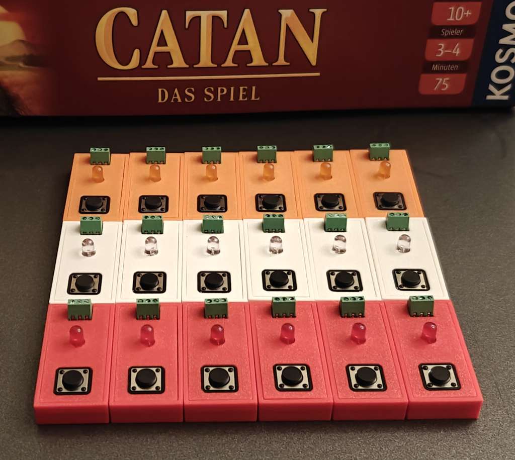
This remote is intended to be used in large Settlers of Catan tournaments. It was made to be cheap to mass-produce, simple to connect and not rely on Wifi or Bluetooth. Since it is not a general purpose remote, we can fix the colors of the remotes to the four colors of Catan: blue, red, white and orange. However, it would be simple to adjust the build and code to support a general purpose remote.
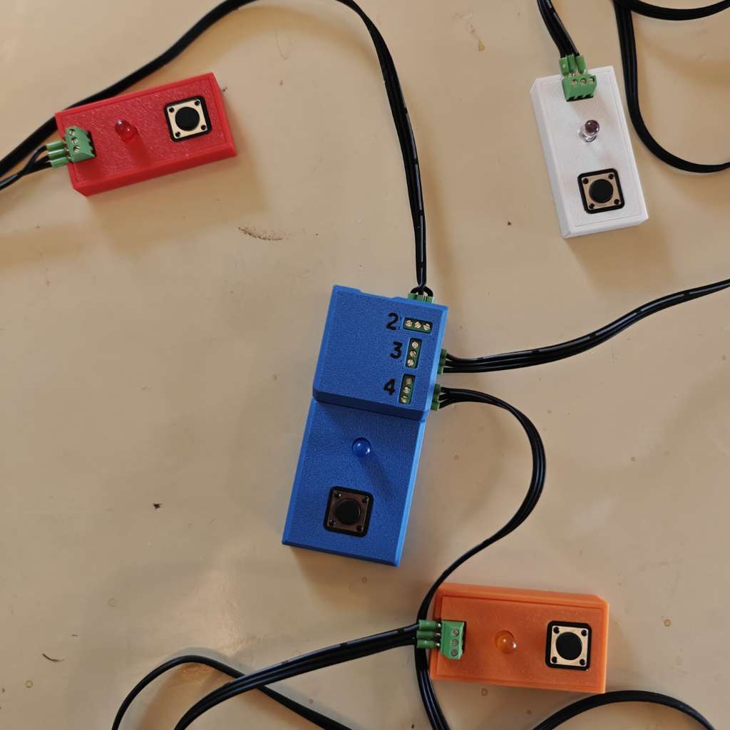
The remote is actually four remotes: one master remote and three smaller slave remotes. The master remote is connected via a USB wire to a phone, tablet or laptop running the Shared Game Timer. The three slave remotes are connected to the master via wires. Each remote has a button (for ending your turn) and an LED (for indicating whose turn it is). The master remote also has the microcontroller unit (MCU) which is the brain of the remote.
The Shared Game Timer has several ways that it can interface with hardware: bluetooth, wifi, keyboards etc. This remote uses the wired USB Serial interface. At the time of writing, only Chrome browsers running on Android phones or a desktop/laptop will work. (See WebUSB / WebSerial for latest support.)
This guide will demo the remote, and then describe how you can make one for yourself! If you ever need any help, please feel free to email me. I'm happy to help!
Demo and usage
This video shows what the finished remote looks like and how it works. Basically, it is a demo of what we will get at the end of this guide!
When the remotes are first powered up, it will be in stand-by mode. Buttons won't do anything, and the lights are off with occasional flashes of light on all remotes to show it is working.
When you start a game, in the 'Game Creation' screen, it will turn on the lights of the found players. So, if you add a red player, it will turn on the red light, and so on.
This is an important point. The remotes are assigned to players by the player colors. If you add a green player, it will not get a player. This is different from how other SGT remotes work, which uses the concept of 'seats'. It is easy to alter the code for it to go back to the 'seat' assignment, in which case it will work for any player colors. But, this code was meant for Settlers of Catan, so using color-assigment made things easier.
When the game is in progress, it will light up the LED of the active player. The active player can end their turn by pressing their button. The LED will either be solid or pulsate. It will pulsate if the game uses Count-Down time mode, and the player is currently in Delay Time. Otherwise, the light will be solid.
Any player can long-press their button to put the game into Admin Time, interrupting the active turn to deal with some kind of admin task. The active player (whose turn was interrupted) is dim with occasional flashes. The active player can press their button to resume their turn. (or any player can long-press again)
If the game is paused, the lights behave similar to when in stand-by mode, but only the active player (whose turn was paused) does the occasional flashes.
When the game has ended, again, it behaves like during the 'Game Creation', with only the players who was in the game having their lights active.
Components
These are the components that make up the remotes. Many of these are cheap components sold in bulk that you may already have lying around if you have done electronics work before. If not, then you will have a lot of leftovers for future projects!
This first list is the stuff that make up the remotes. I have not written out the quantities, but it should be pretty obvious when you need one and when you need four (one for each button).
.jpg) Seeed Studio XIAO RP2350 (Pre-Soldered)
Seeed Studio XIAO RP2350 (Pre-Soldered) 5 mm LEDs
 Resistors
 12 mm Buttons
 3-pin Terminal Blocks
 3cm x 7cm Fibreglass Perf Board
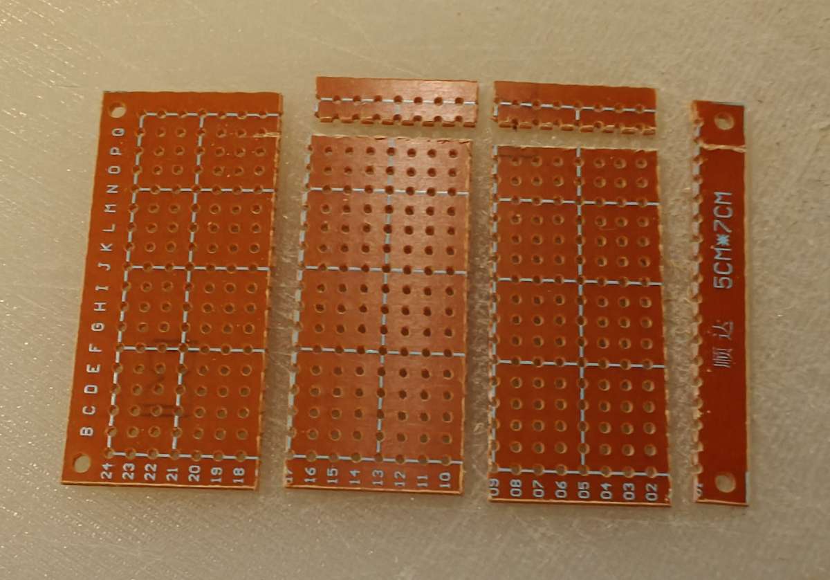
 5cm x 7cm Bakelite Perf Board
 26 AWG 3 Pin Ribbon Cable
 Wire End Ferrules 0.25 mm2
 22 AWG Solid Wire
The list below are the tools that I used to build the remotes. Again, you may have some of these already, if not, then this is a great way to start your own home lab!
 Wire Stripper
 Steel Ruler
 Cutter Knife
 Soldering Mat
 Flush Cutter
.jpg) Crimping Pliers (AWG28-5)
Crimping Pliers (AWG28-5) Digital Multimeter
 Third Hand
 Soldering Iron Set
 Soldering Flux and Desoldering Wire
 Breadboard
.jpg) 3D Printer (multi-material)
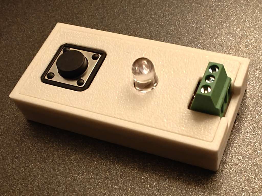
3D Printer (multi-material)3D printing the enclosure
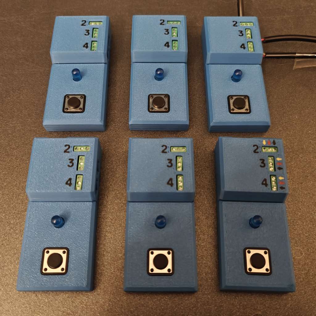
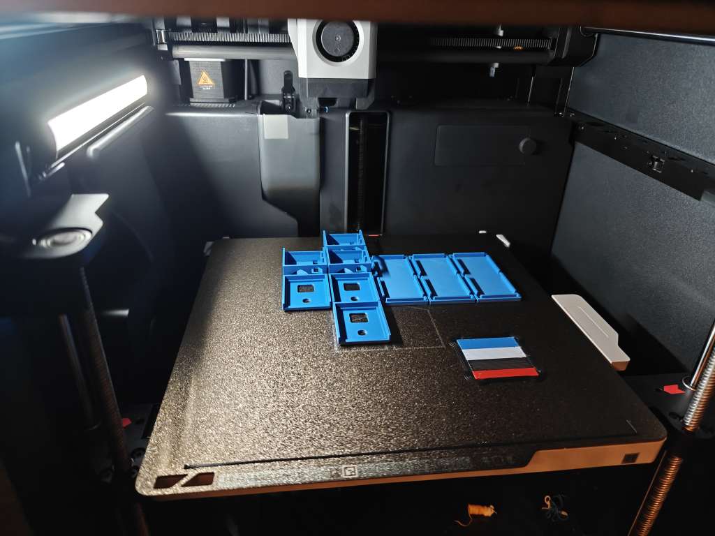
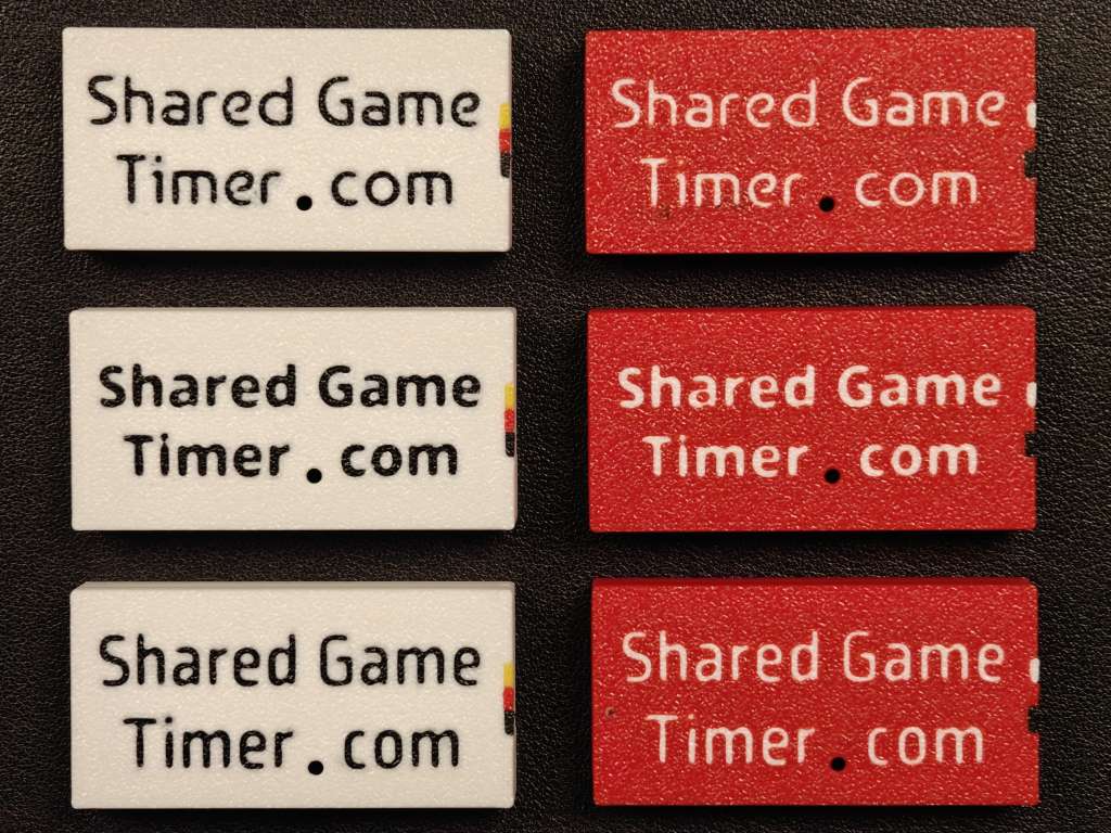
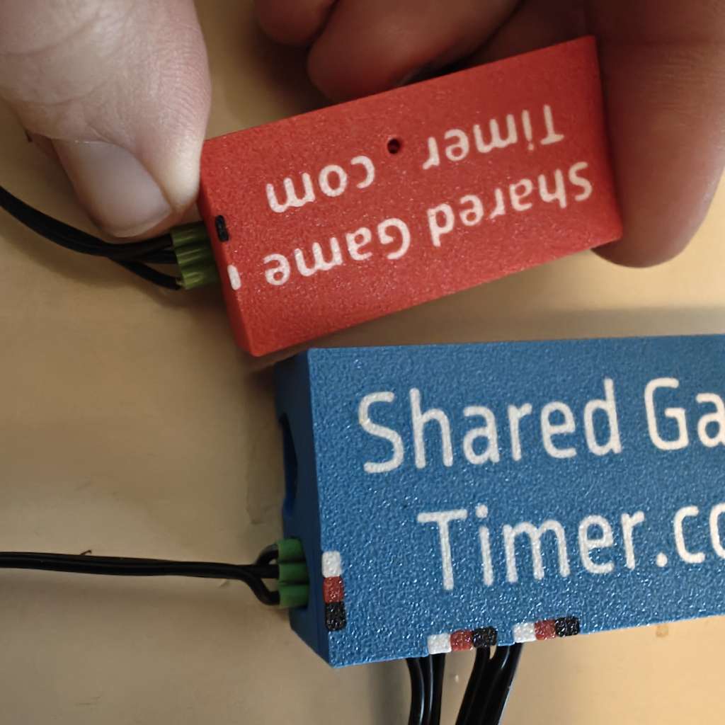
I printed the enclosure using a Bambu P1S with an AMS. If you don't have an AMS, just print it as is in one color per remote. With an AMS, you can pick different colors for the text (if you want it) and mark the way the wires go (white/yellow for the button signal, red for the LED pin, black/blue for ground)
It can be a good idea to print the enclosures first so that you can make sure the boards will fit before you start soldering.
- 3D Print Files as 3MF (master & slaves)
- OnShape document for the master remote
- OnShape document for the slave remotes
Selecting resistors
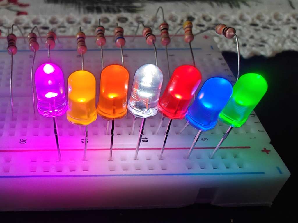
It is worth testing the LEDs and the resistor combinations before soldering them to the circuit board. Sometimes LEDs are broken, and then you can pick another one. Also, you should be happy with the strength of the resistors you want to use. The choice of resistor makes the LEDs brighter or dimmer. Note that if you pick a too small resistor, you will burn out the LED.
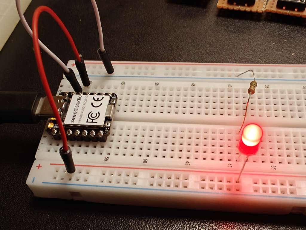
Have a look at this guide to learn more about LEDs and how to test them. Using the RP2350, the easist way to do this is to wire multiple resistor/LED pairs in parallell between the 3.3 V pin and GND.
- Connect the 3.3 V pin and GND pin to opposite side-rails on a breadboard.
- From the 3.3 V rail, add various resistors in increasing strength that jump the middle divide to some evenly spaced rows.
- Add the resistors you want to test at your best guess of resistor values by putting the LED cathode (short leg) in the GND rail and the anode (long leg) in the row of the resistor.
- Apply power and the LEDs should light up. Too bright? Move to a higher value resistor. Too dim, do the opposite.
Below are the resistor values I picked for my LEDs.
| Color / Fwd V. | Fwd. Voltage | Resistance |
|---|---|---|
| Red | 2.1 V | 150 Ω |
| Blue | 3.1 V | 330 Ω |
| White | 3.1 V | 1000 Ω |
| Orange | 1.9 V | 220 Ω |
Assembling the slave remotes
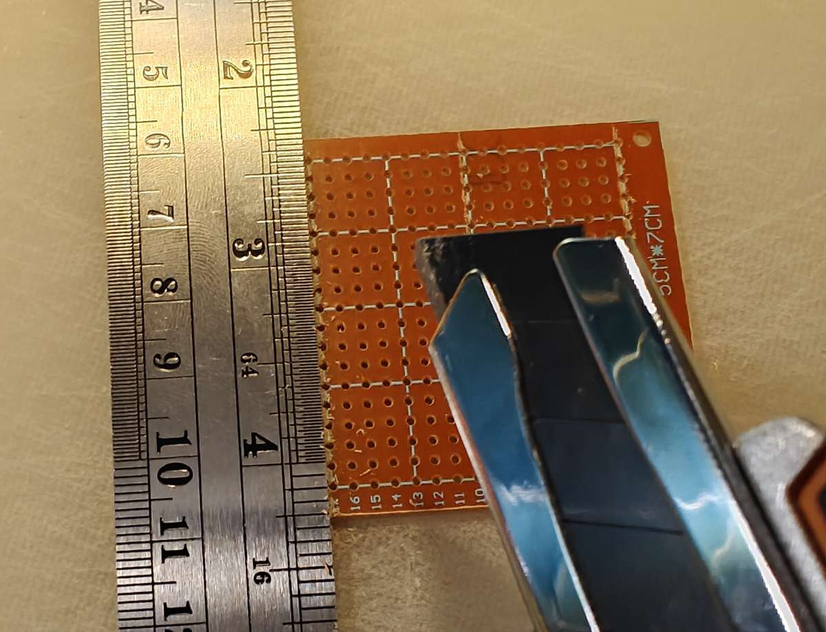
The master remote is assembled on the bakelite perfboards. However, you must cut them to the correct size. You could do this on fibreglass boards, but it is a bit harder and comes with the issue of fibreglass fibres, which is why I used bakelite.
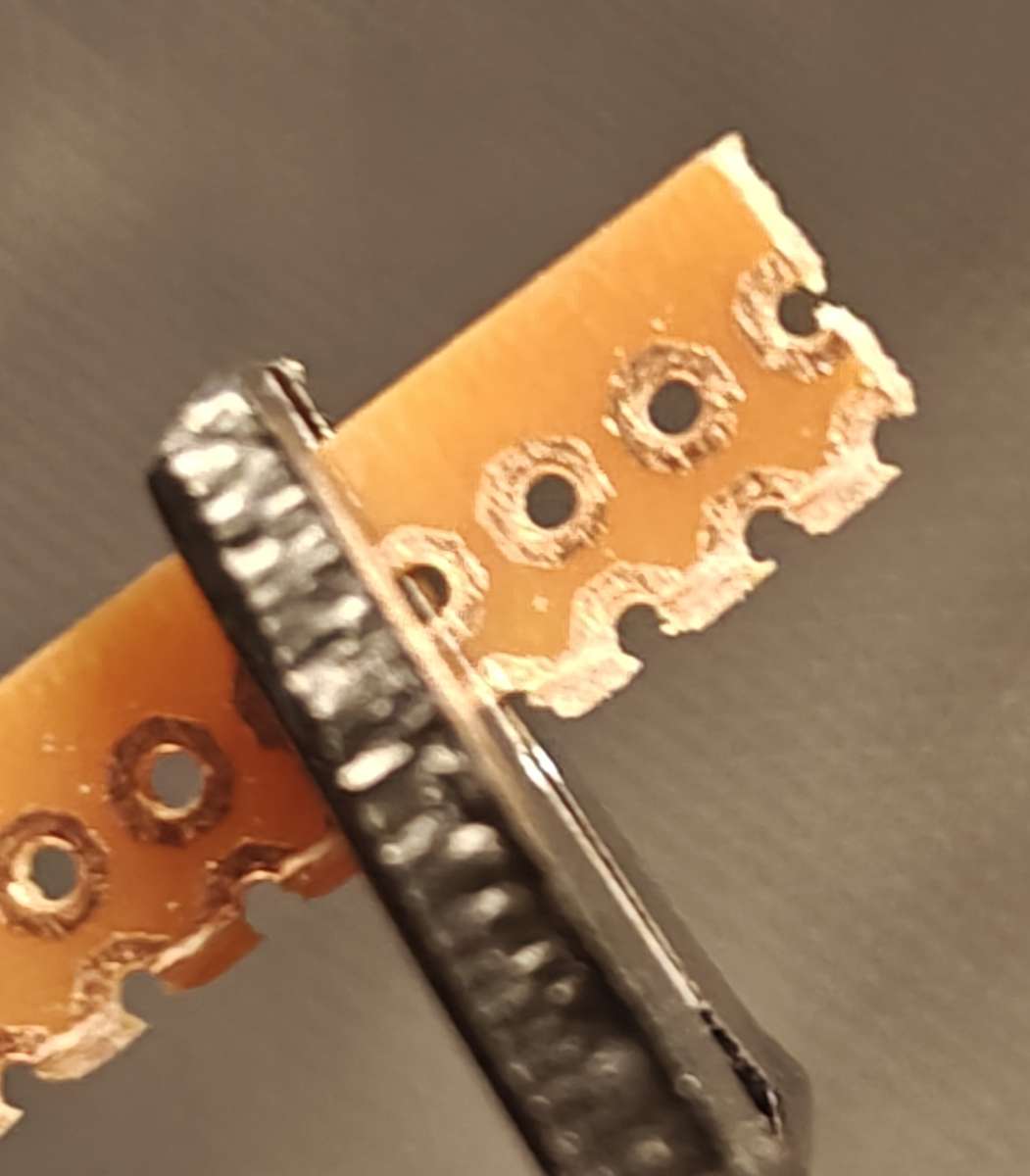
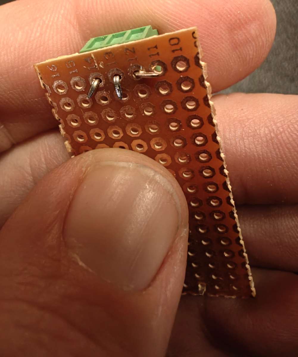
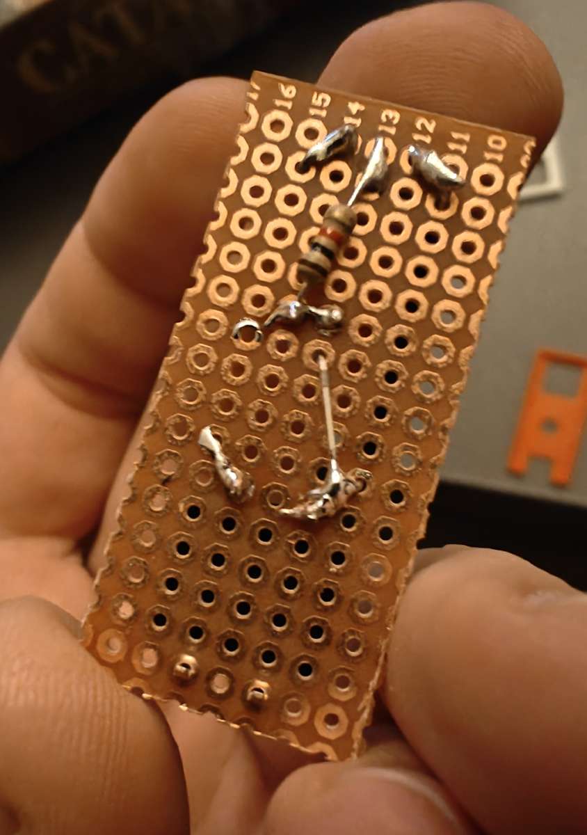
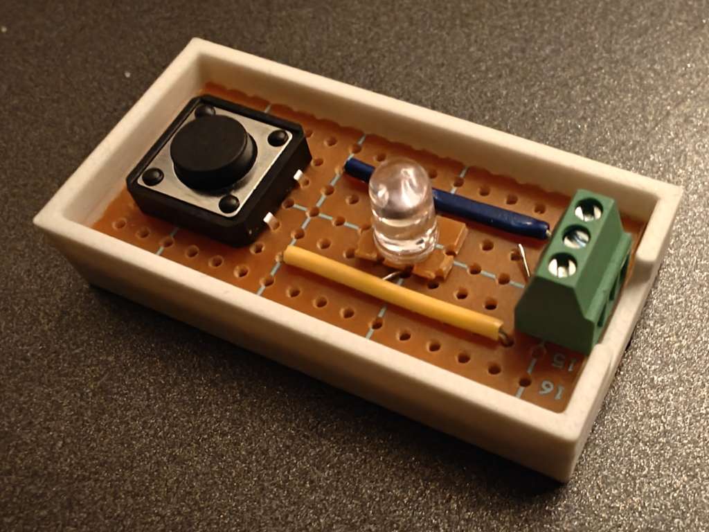
- Use the steel ruler and the cutting knife to score lines on both sides of the bakelite board, then bend to snap-break the board along the score line. Be careful with your fingers! The resulting board should have 7*16 intact holes. Look at the images to see how to cut the board.
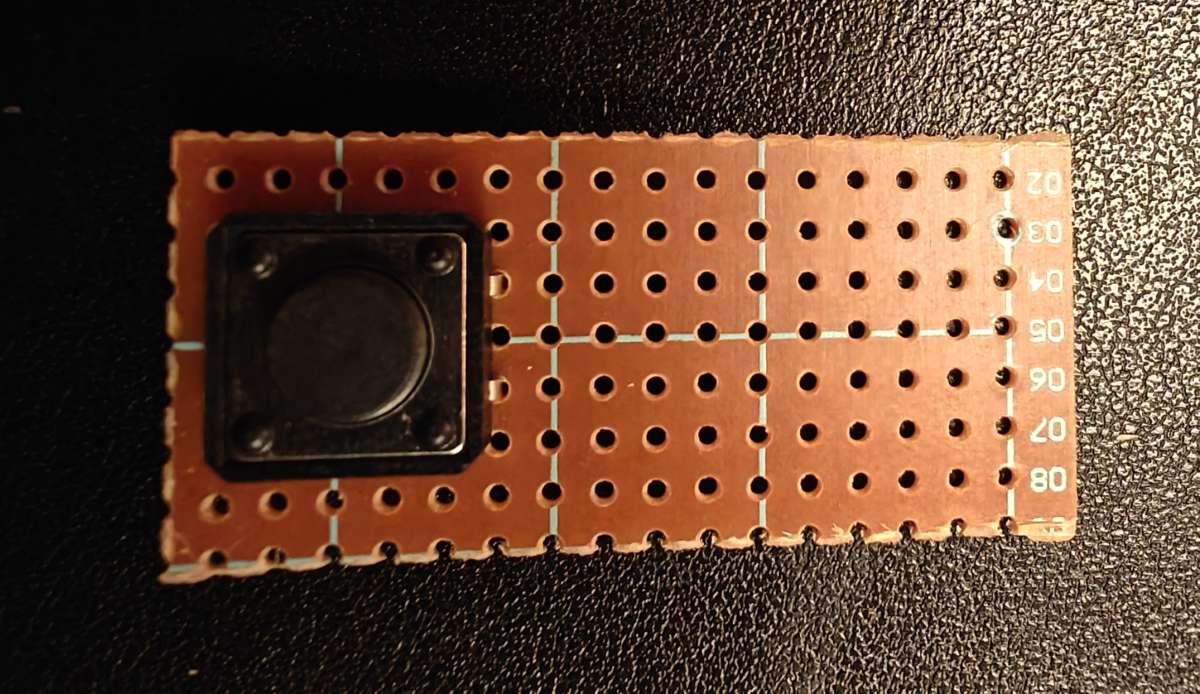
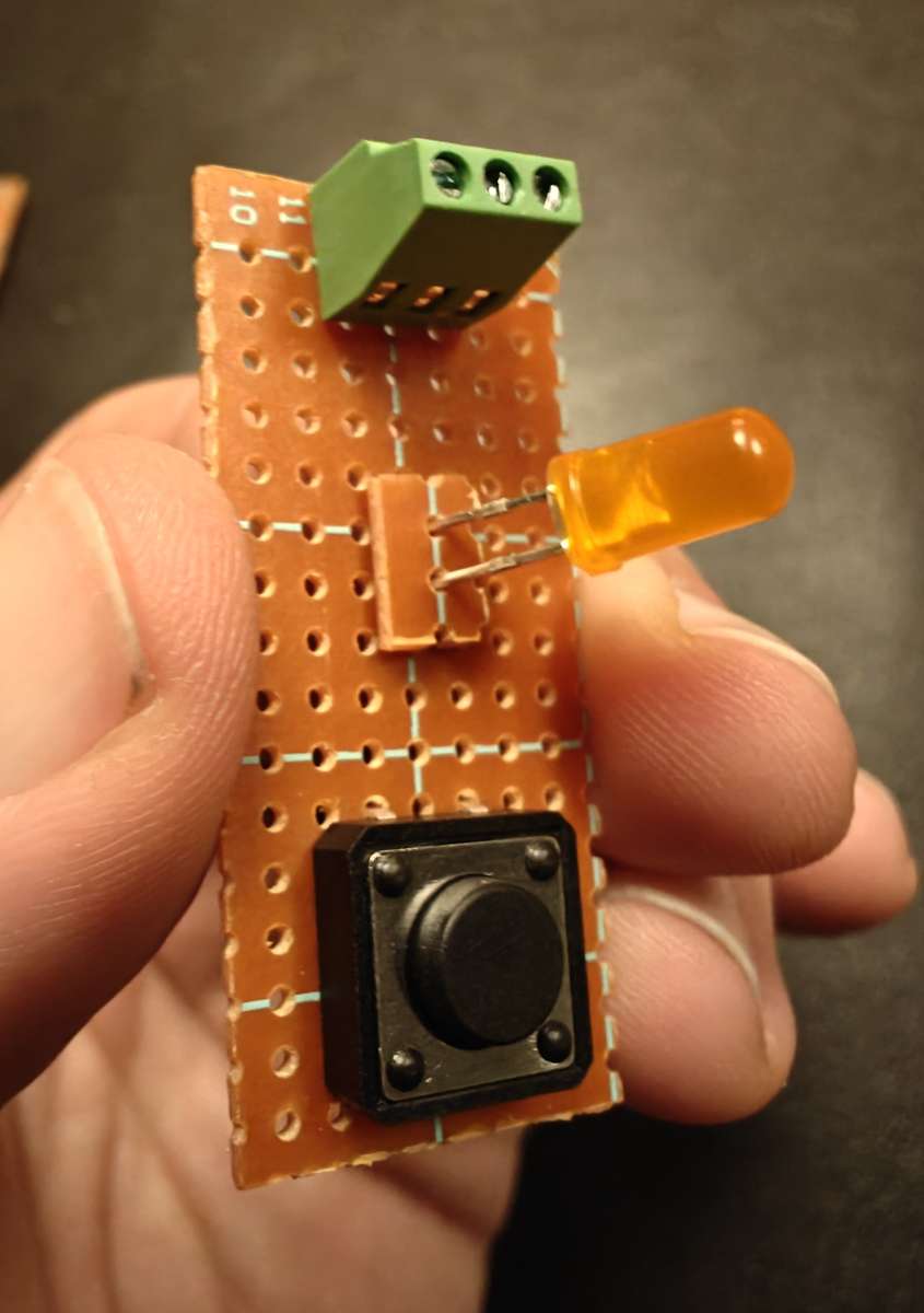
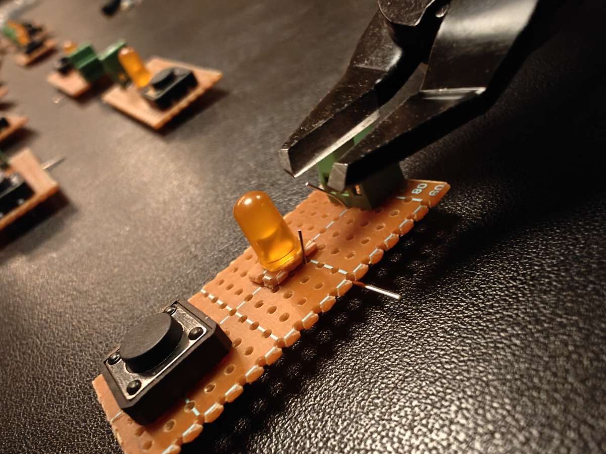
- Place the button as shown on the image. Be careful when pushing the legs through as they could bend the wrong way.
- From the leftover thin strips of bakelite board, cut a small piece leaving 1x2 intact holes. This piece will be used as a 'pedistal' for the LED to stand on.
- Pick the relevant LED color (red, white, orange). Thread the 'pedistal' over the LED's two legs, then insert the LED in the middle row of the board, as shown on the image. Make sure the cathode (short leg) is closest to the button. Turn the board over and bend the LED legs to secure the LED. Bend the cathode so it touches the button leg as shown on the image.
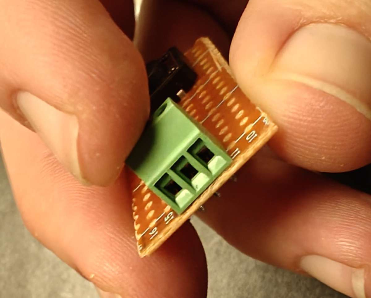
- Put the 3-pin terminal block opposite of the button with the holes pointing away from the board. Turn the board over and bend the middle leg towards the board, and the other pins towars the sides, if possible. This is to secure it in place while soldering.
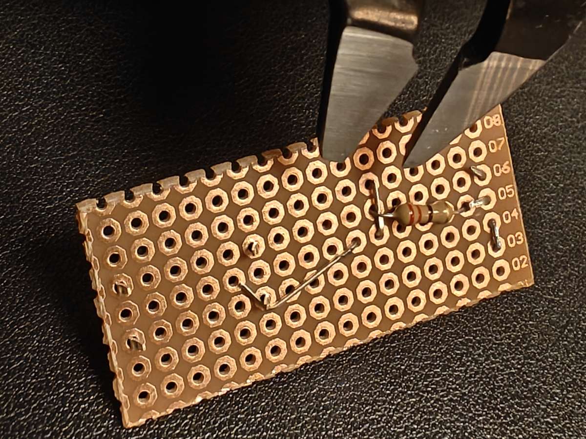
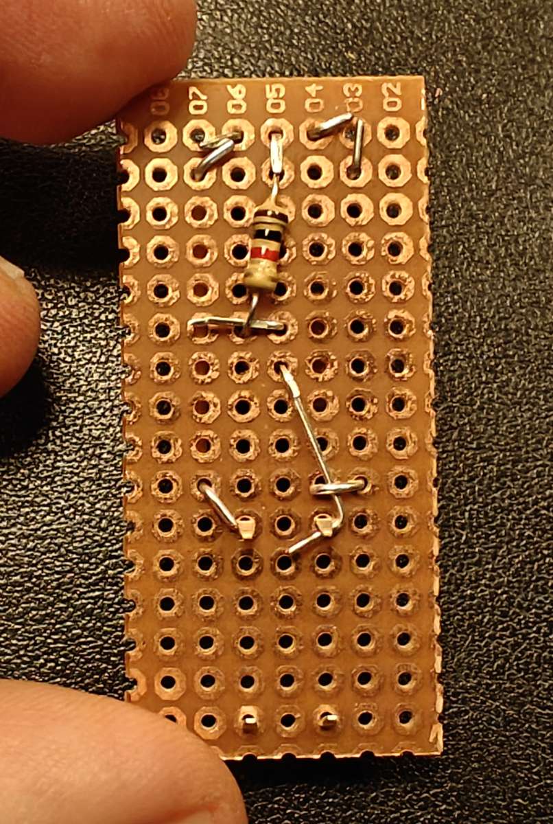
- Take the resistor you picked for the chosen LED and thread it from the bottom of the board as shown. You want the legs as close to the LED anode (long leg) and terminal block middle leg as possible to make soldering easier. On the top side, bend the resistor legs to secure it while soldering.
- Use the flush cutter to cut off excess legs. Don't worry about getting it too neat. It will all be hidden later.
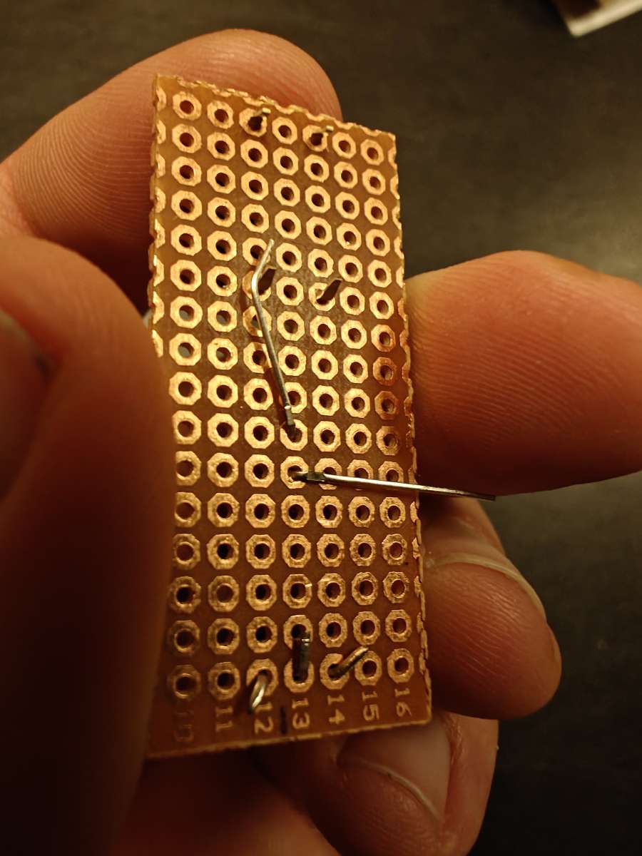
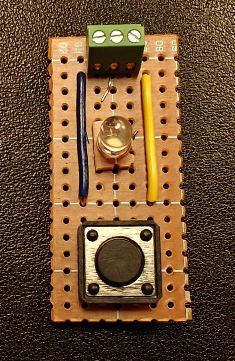
- Cut two 3 cm long jumper wires (22 AWG solid core), strip the ends using the wire stripper, bend and insert from the top of the board as shown on the image to connect the sides of the terminal block to the corresponding sides of the button. Bend the legs to secure them in place for soldering, and as close to the button and terminal block legs as possible.
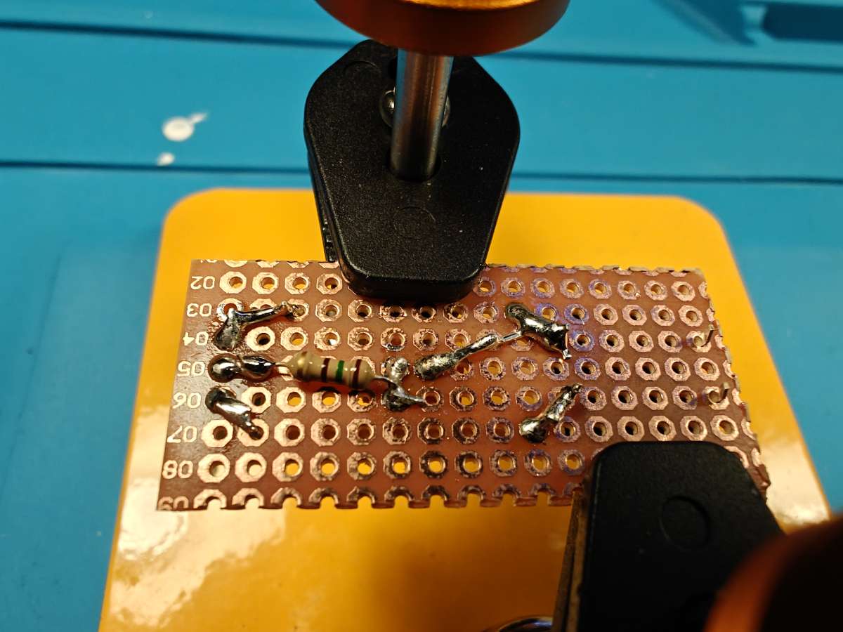
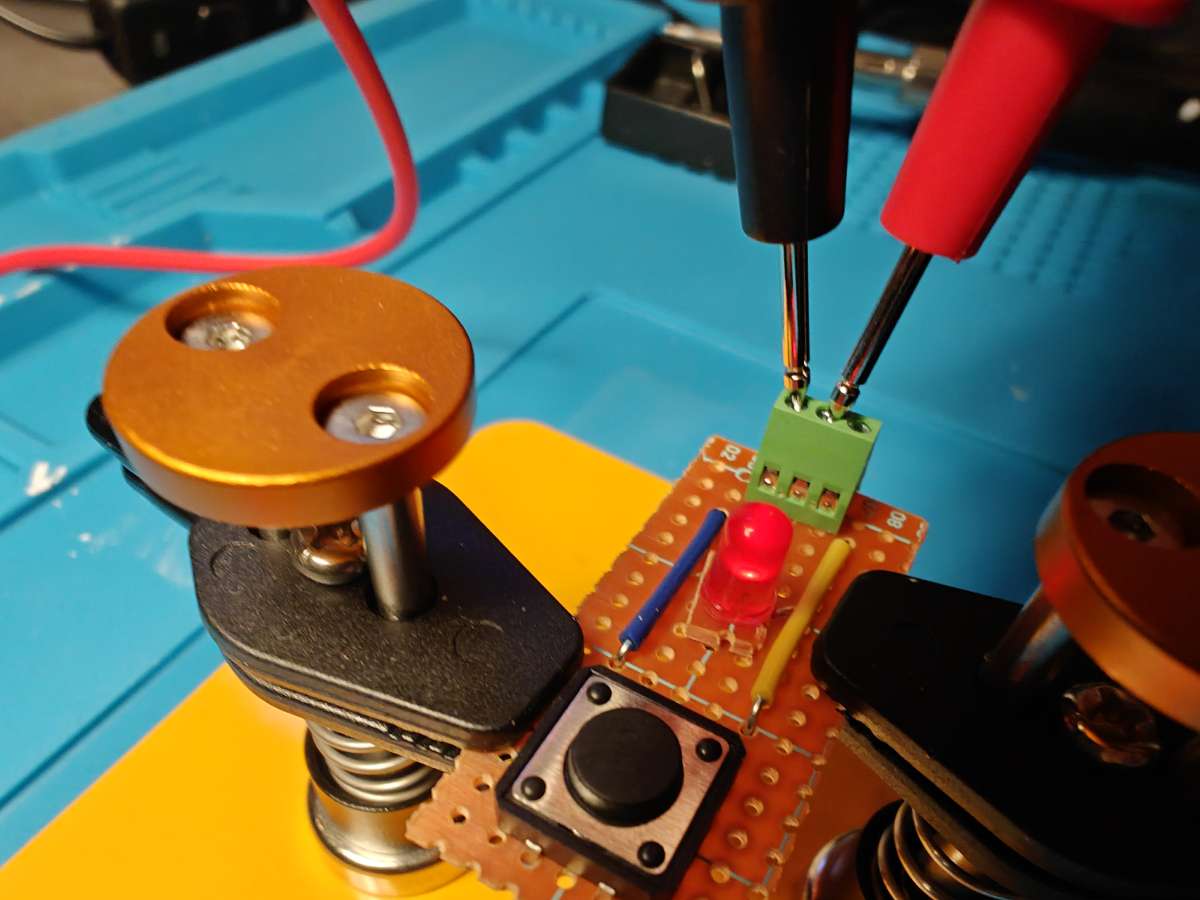
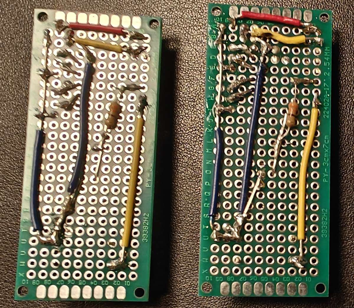
- Time to solder! I've included some images of my soldering setup, but yours might be different of course. You can see there what soldering joints to make. (Resistor to middle terminal block and LED anode [long leg]. One button leg should connect to the LED cathode [short leg] and the nearest jumper wire that goes to the terminal block. The other button leg should go to the other jumper wire. Both jumper wires should connec to their respective terminal block sides. Honestly, the image is way easier to understand!)
- Before wrapping up, it is useful to check your soldering using a multimeter. Check the connections that should exist but also check that there is no connection between things that should not be connected, especially the three terminal block pins. See the images.
Assembling the master remote
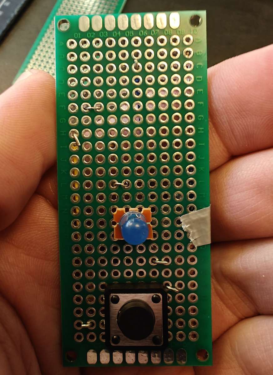
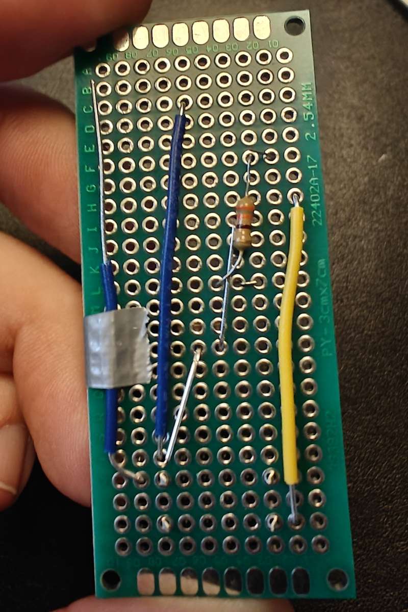
The master remote is assembled on a 3 cm * 7 cm fibreglass perfboard. It is definitely more fiddly to make than the slave remotes. Some of the jumper wires cannot be bent to secure when soldering and have to be secured by tape. The tape will melt very quickly when you start soldering. And, the soldering joints around the MCU are very close together. Use small amount of solder or you will have to use solder wick to clean up the mess. (ask me how I know...)
- Place the button in the middle with the legs centered on the second and fourth row from the bottom.
- Place the blue LED on the LED pedistal you used for the slave remote and place it on row 10 (O) with the short leg (cathode) pointing towards the right (the side that will have all the terminal blocks) Bend the short leg towards the button leg on 'its side'. The long leg (anode) you can bend kinda upwards.
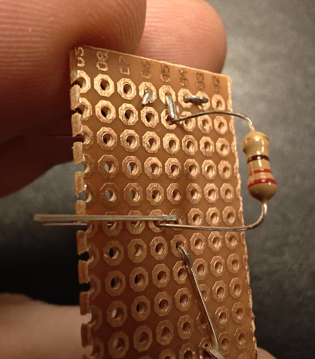
- Thread the resistor from the bottom so that you can easily solder one end onto the LED anode and the other to a terminal pin which will be bent inwards from hole F1.
- Make a yellow jumper wire that goes from H1 to W2. Make a blue jumper wire that goes from C6 to any hole near the LED short leg (cathode). Bend the wires on the top side to secure them for soldering.
- Make a long blue jumper wire that goes from somewhere near the LED cathode up via I10 and all the way up to, but not through, A10. Strip the wire so it is bare from I10 to A10. This is a ground wire that will be connected to by the three terminal blocks. There isn't space for it to go through a hole and bent to secure it, so use tape to hold it in place.
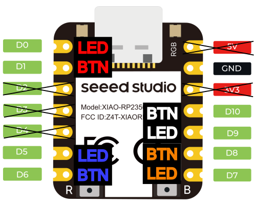
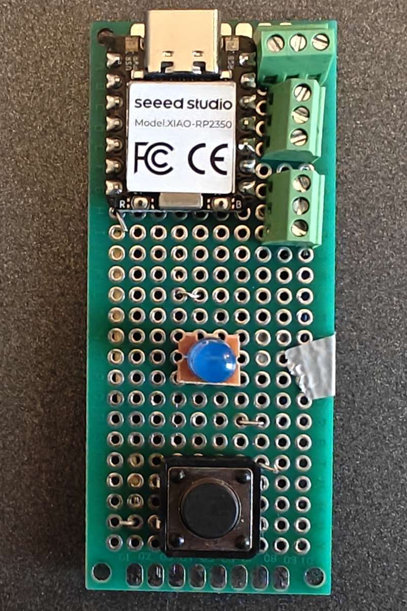
- Look at the pin out of the RP2350 and cut away the unused pins. It will be easier to solder with them out of the way. (D2, D3, D4, 5V, 3V)
- Put the XIAO RP2350 and terminal blocks in place. Now it is time to do some bending of pins to hold things in place, and prepare for soldering.
- Bend D6 towards the jumper wire that goes to the button.
- Bend D5 towards the resistor.
- Bend the ground terminal block pins towards the stripped ground jumper wire.
- Bend D7 and D9 towards their respective middle terminal block pins.
- Bend D8 and D10 towards the remaining respective terminal block pins.
- Bend the terminal block pins towards the D7-D10 pins.
- Bend the GND pin of the MCU towards the blue jumper wire at C6.
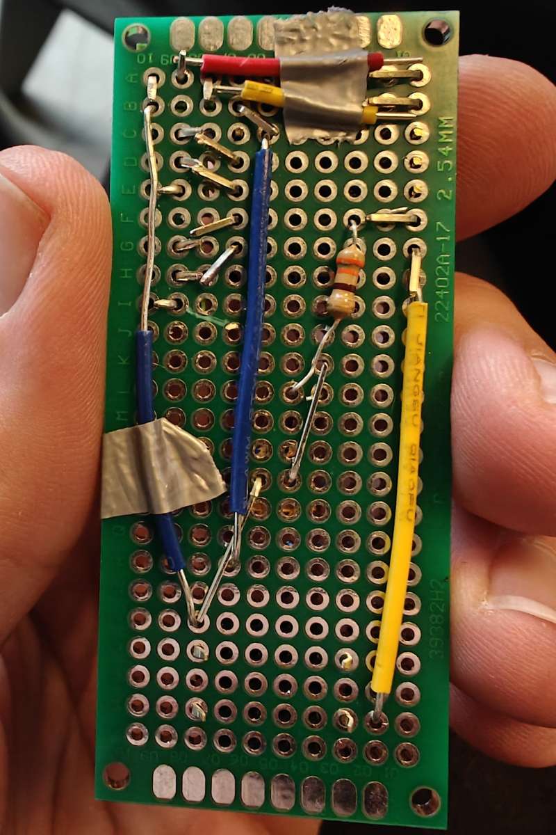
- Cut a red jumper wire that goes from the D0 pin to the middle pin of the top terminal block. The metal of the jumper wire and the pins should touch. It may help to bend the terminal pin upwards. Secure the wire with tape.
- Do the same with a yellow wire from D1 to the remaining terminal pin.
- Solder it all together. Be careful! This is tricky soldering. After, check and double check all the connections and make sure you haven't accidentally soldered the cut-off 5V and 3V pins to anything!
Programming
The remote runs on Circuit Python, and the guide below runs through how to get circuit python on the RP2350, and how to install the code I wrote.
WARNING! READ THIS: The code includes code in the boot.py file that turns off the USB drive mounting unless the blue button (on pin D6) is held down.
This is good as it prevents the 'disk mounted' popups to show up when plugging in the remote, and you can still edit the code by holding down the blue button when connecting the remote. But this might scare you, in case you can delete or comment out all the lines from line 3 and onwards in boot.py.
- Download the CircuitPython .UF2 file for the XIAO RP2350.
- Follow the XIAO RP2350 'Getting Started Guide', to enter the boot loader, but instead of dragging the MicroPython .UF2 file to the bootloader, use the CircuitPython .UF2 file.
- Download the same version of the Circuit Python Libraries that correspond to the .UF2 version you installed. Unzip it, and drag the
adafruit_logging.mpyandadafruit_fancyledto the/libfolder. - Download the SGT Catan code zip file, unzip it and drag the content (
code.py,boot.pyandsrcfolder) to the new CIRCUITPY drive that should have appeared after the last step.
Crimping Wires
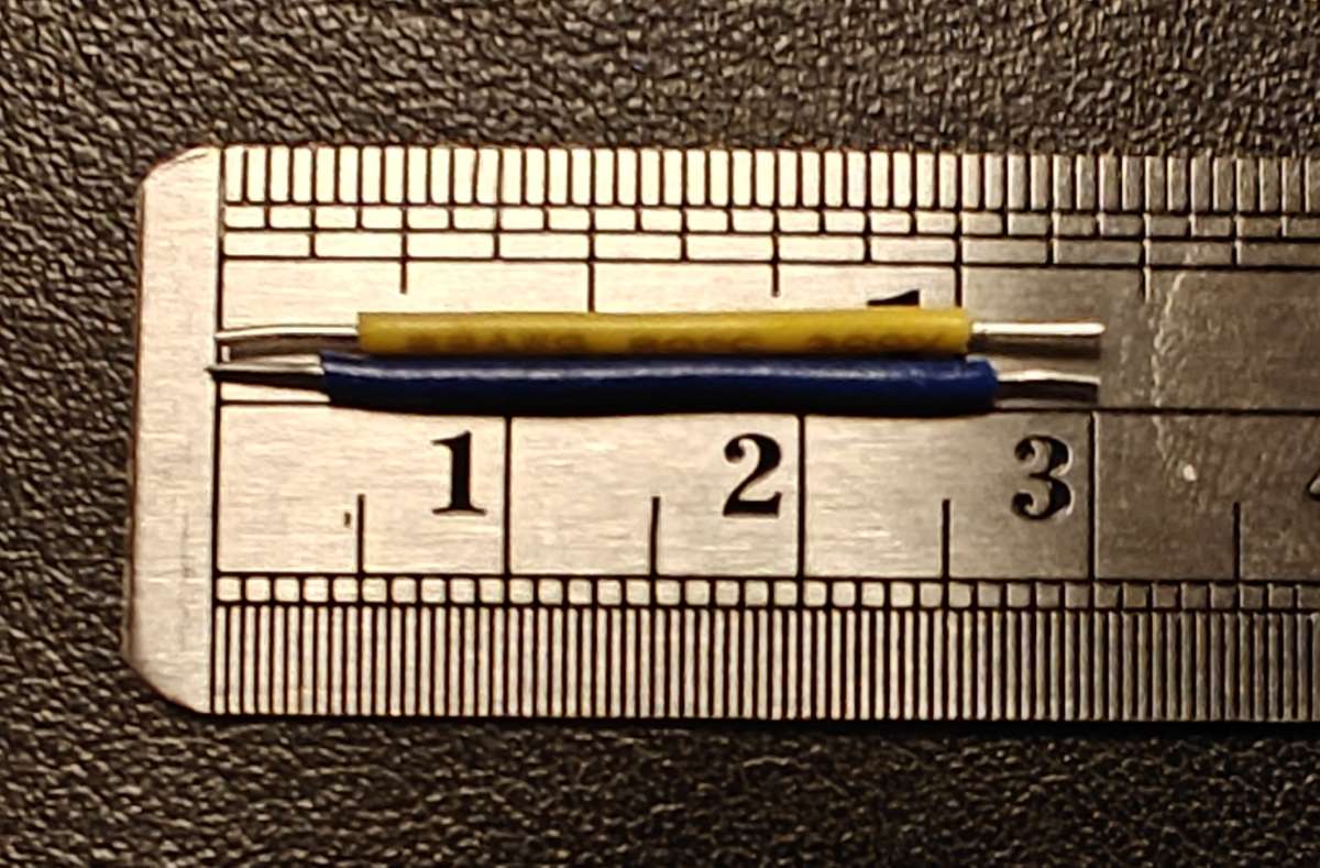
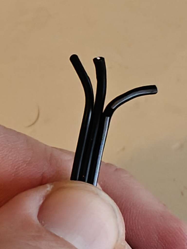
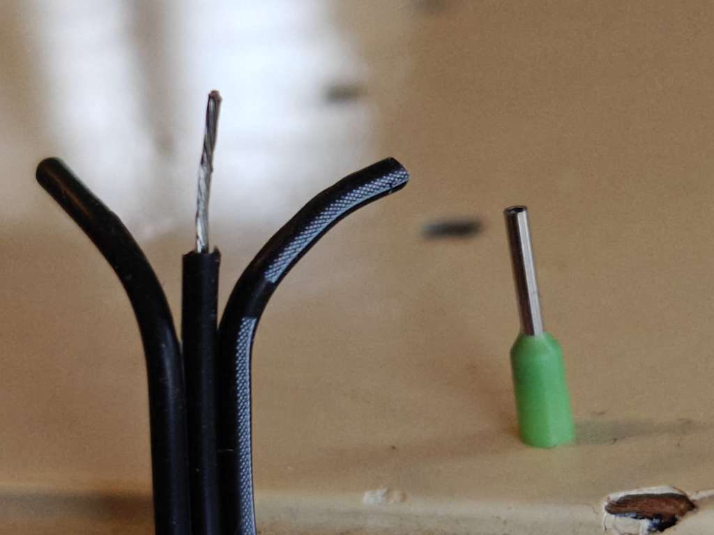
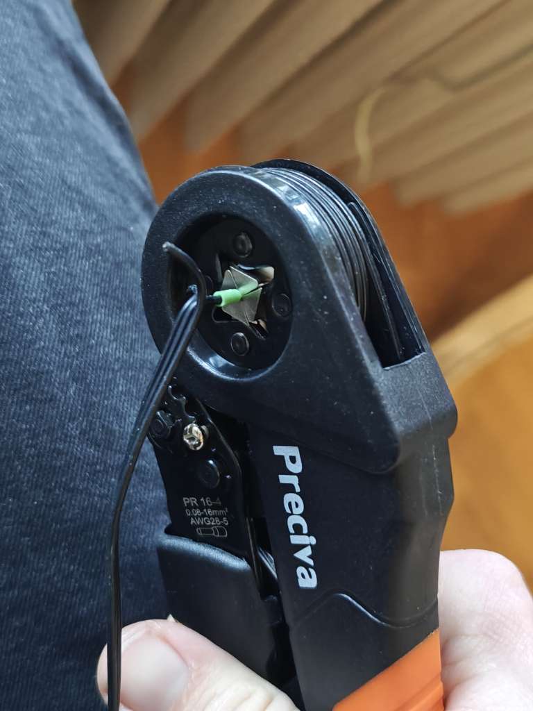
These wires seemed to work best. They are small and flexible. You can try to put them straight into the terminal block, but I found that the connection was a bit flimsy. They could easily be pulled out, or they would not keep the connection very well, or even short-circuit. Try it, but if you want a better connection, then you want to crimp ferrules onto the end of the wires.
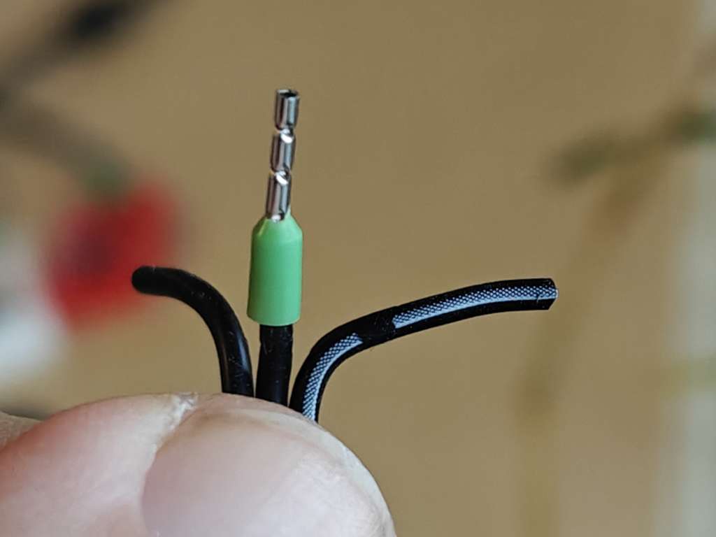
- (optional) Shorten the green protective plastic of the ferrule.
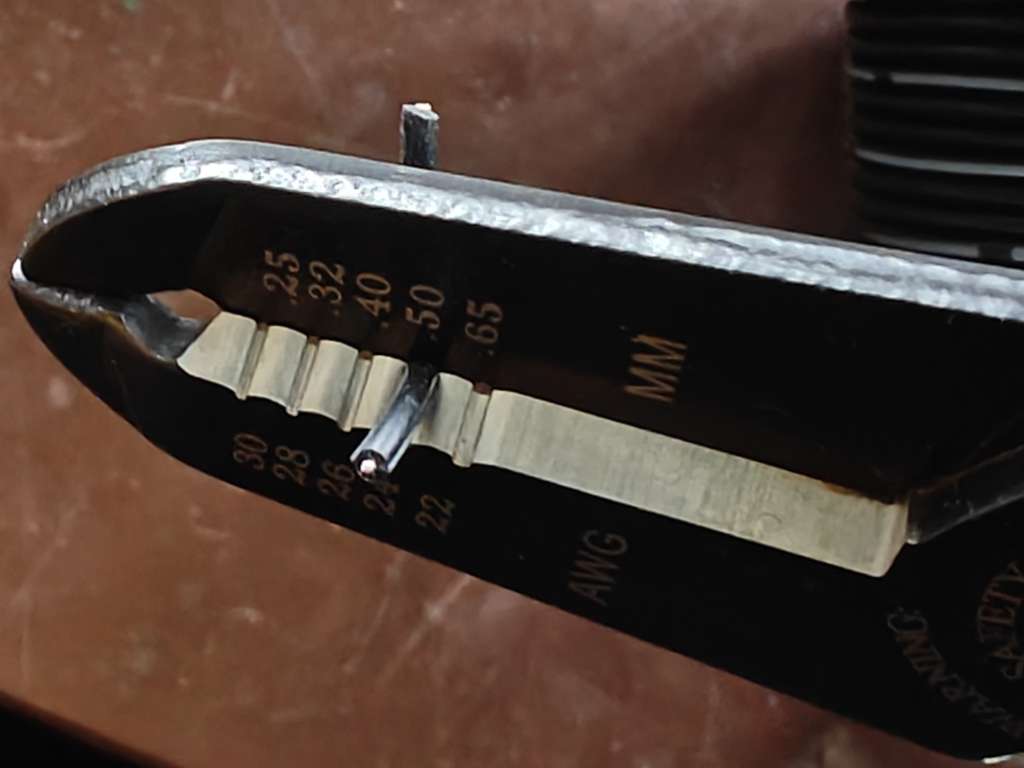
- Use the wire stripper to remove a bit of the sleeve, about the length of the metal part of the ferrule.
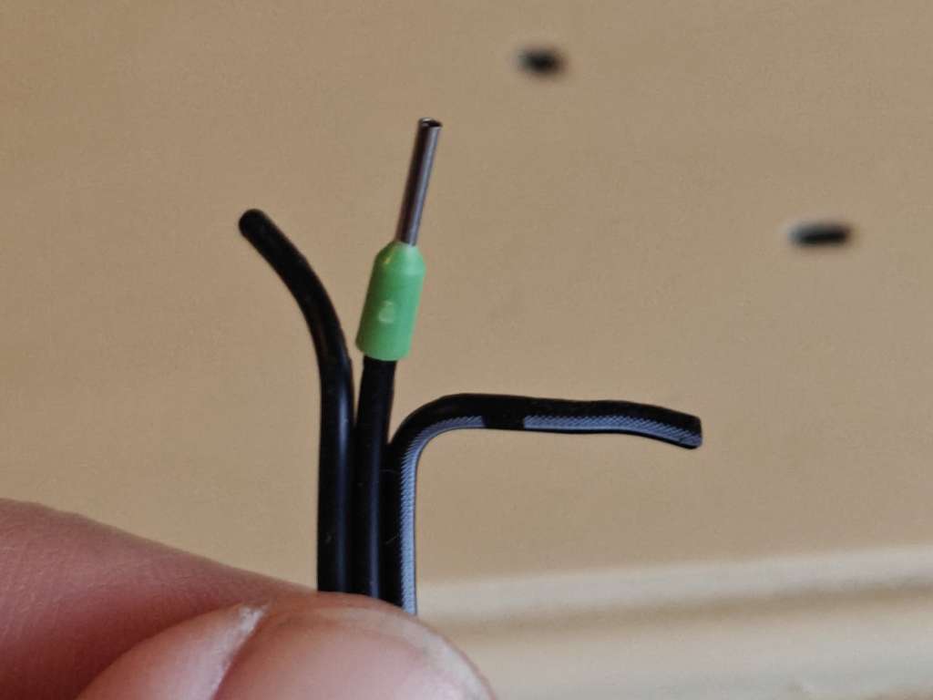
- Twist the wires together and insert into the ferrule.
- Use the crimping tool to crimp the metal tube of the ferrule over the stranded wire.
- With all the six ferrules crimped onto the wire (three on each side), screw the wires into the terminal block. Use the white stripe on one side to make sure the wires match up between the master and slave.
Connecting to the Shared Game Timer
At the time of writing, only Chrome browsers running on Android phones or a desktop/laptop will work. (See WebUSB / WebSerial for latest support.)
- Connect the master remote to your SGT device.
- In the create-game screen, scroll to the bottom and click 'Setup Remote Controls'. Or, if you are in an active game, open the menu and click 'Remote Control'.
- Open the 'Setup USB Serial' menu.
- If on Android, click 'Try Web USB' and in the popup, select the RP2350 option. If on desktop, try 'Web Serial' and select one of the ports that mention CircuitPython. If that doesn't work, try the other.
- The remote should now show up as Connected. You can now return to the game creation/game page. It should now be working.