Pill Button
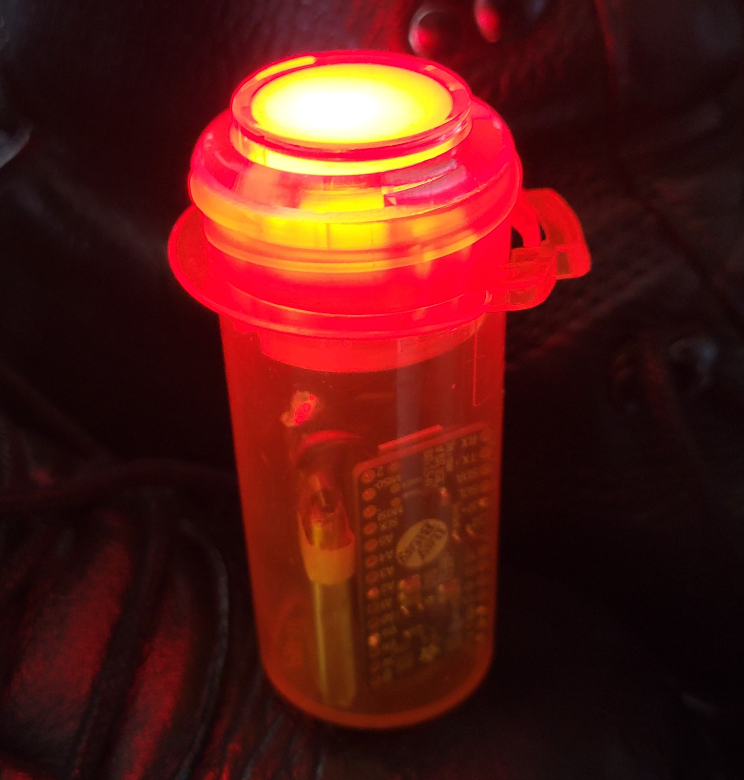
This guide shows how you can build a cool Bluetooth-enabled general-purpose button housed in a pill bottle. The button can easily be programmed to function as a remote button for the Shared Game Timer (or anything else). The button has a programmable RGB LED that can for example show the current player's color.
Overview
In this guide, we will make a programmable button housed in a standard pharmacy pill bottle, something probably a lot of people have lying around, at least in the United States.
It will have a single button which we can program to do 'stuff' when pressed, double pressed, long pressed and so on. Of course, the way I intend to use it is as a remote control for the Shared Game Timer, but you can make it do anything you like over Bluetooth.
We will also make the button backlit by a programmable LED light, so the button can change color, perfect to show who the current player is!
Components
The main component is of course the pill bottle itself! I found one lying around at home, and hopefully you do too. Especially if you live in the US, they seem to be in every home. If not, ask around at a pharmacy.
The bottle I used is 73mm tall (not counting the lid) and has an inside diameter of 30mm. Getting the exact measures right is less important if you go with the final 'button in lid' approach. If you want to try the lidless option, then try fitting the arcade button into the bottle before you do all the other assembly.
Below is the shopping list for the electronics. You will also need soldering equipment. Check out the Adafruit Guide to Excellent Soldering for help on that.
 Adafruit ItsyBitsy nRF52840 Express
 Adafruit LiIon/LiPoly Backpack
 Arcade Button - 30mm Translucent Clear
 NeoPixel Mini Button PCB
 LiPo Battery with Short Cable - 3.7V 350mAh
 Breadboard-friendly SPDT Slide Switch
 Silicone Cover Stranded-Core - 26AWG
 Heat Shrink
Creating the LED button
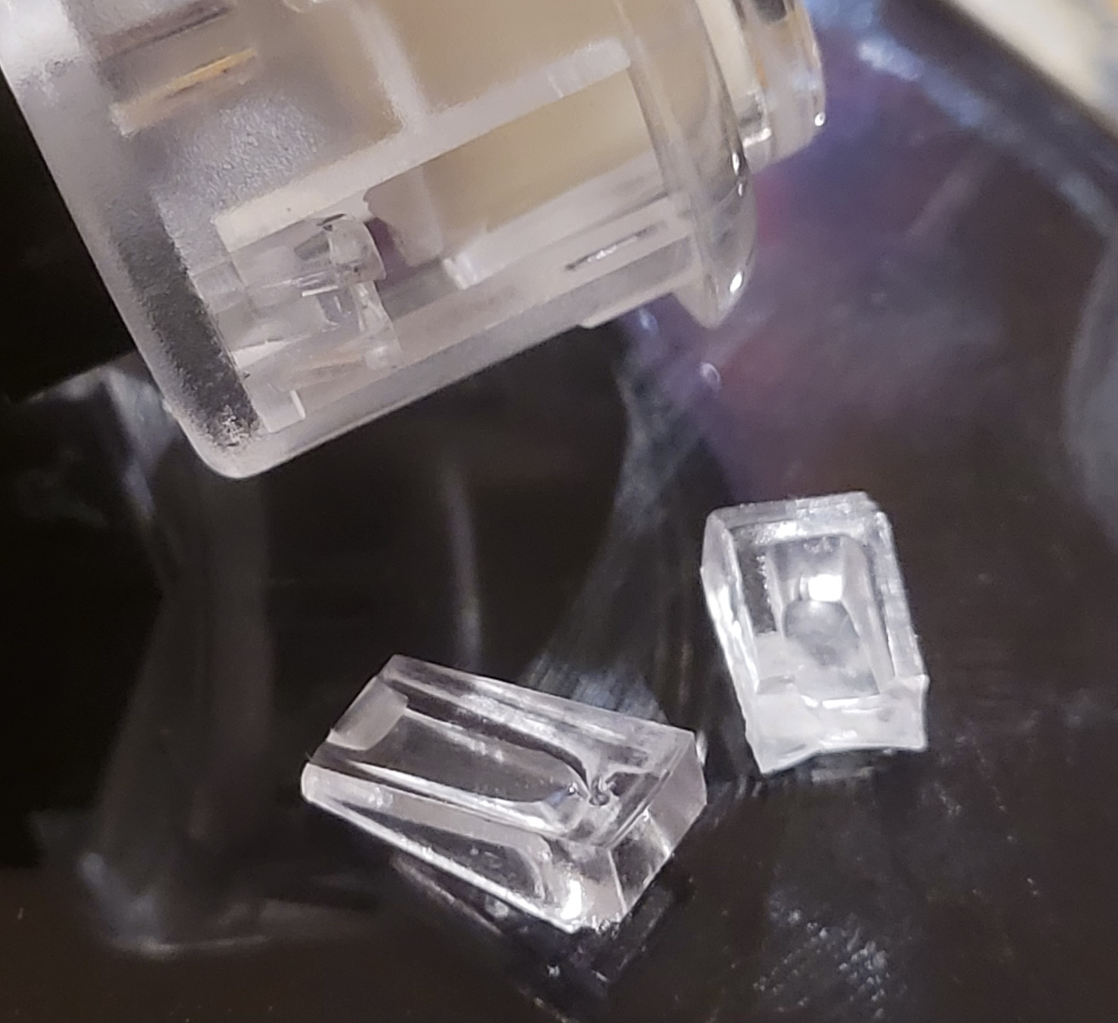
Adafruit has a guide for how to integrate a RGB LED (NeoPixel) into the arcade button so that we can light it with whatever color we choose. In fact, there are two guides that use this technique, and the second one has a slightly different variant of the 3D printed part that holds the NeoPixel. I can't remember which one I eventually used, so print all three versions and see which one works.
You should use as white of a 3D printing material as you can find to get the clearest color.
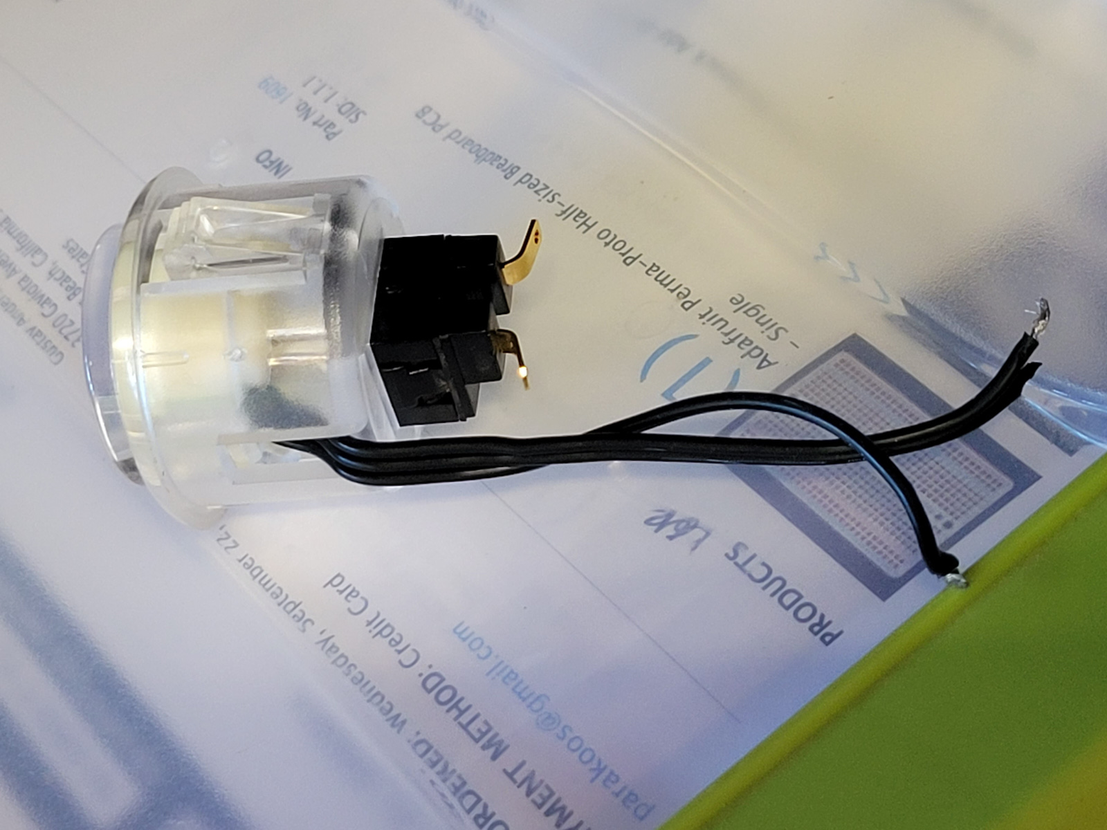
Solder on three wires to the NeoPixel and run it out the arcade button. Make sure you know which wire is power, signal and ground! I used a 26 AWG ribbon, and set the white-marked ribbon to power, and I could then remember that the middle was signal, and the last one was ground. Or just use differently colored wires!
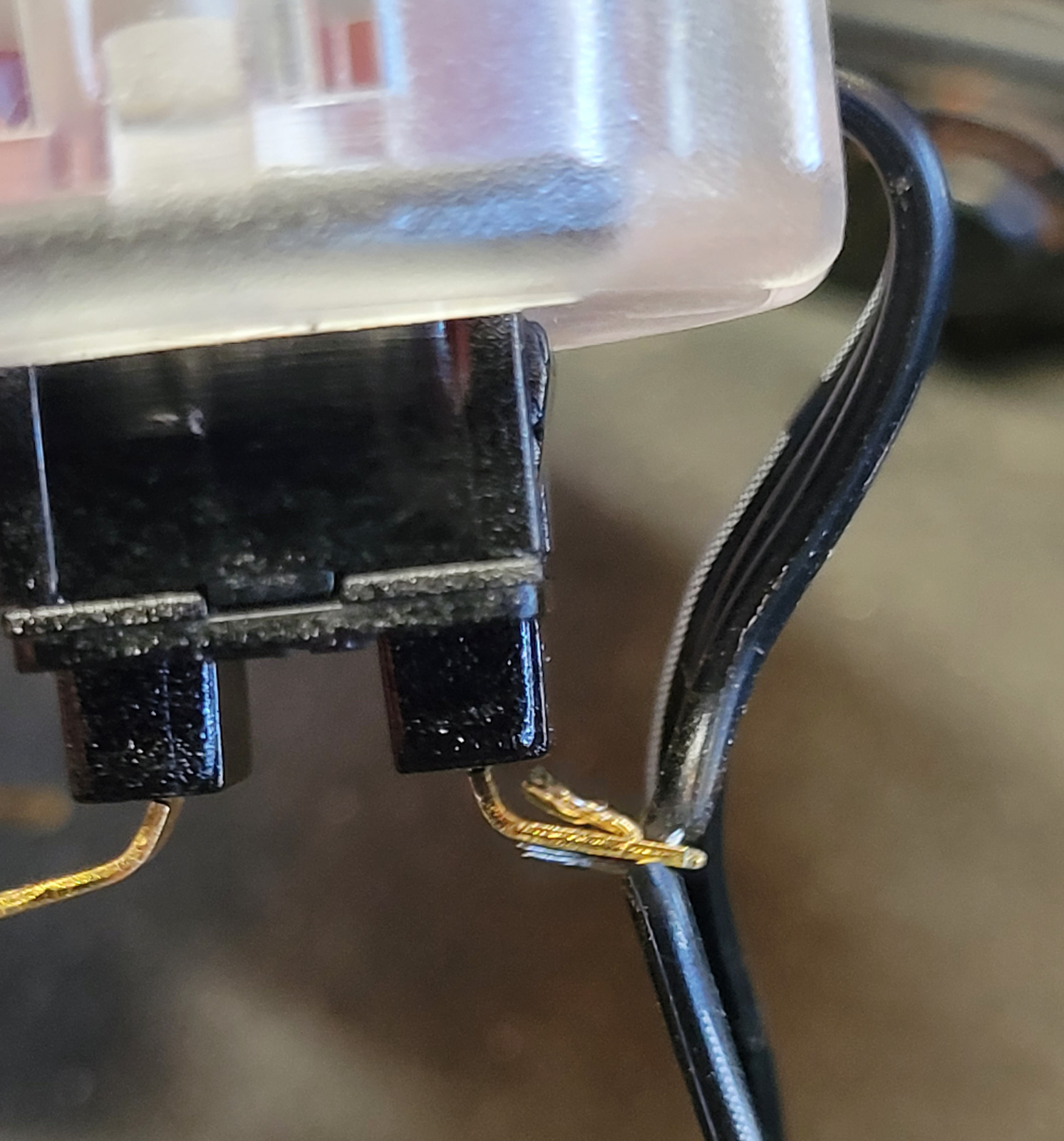
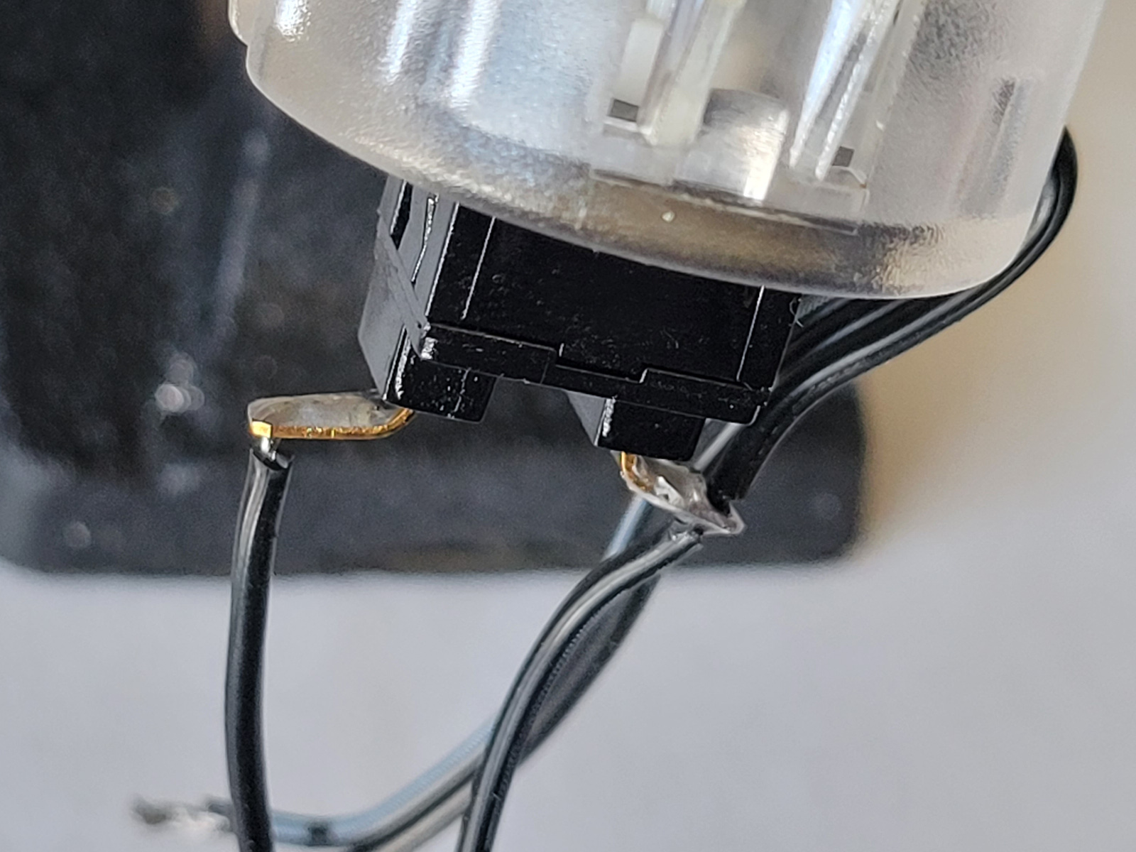
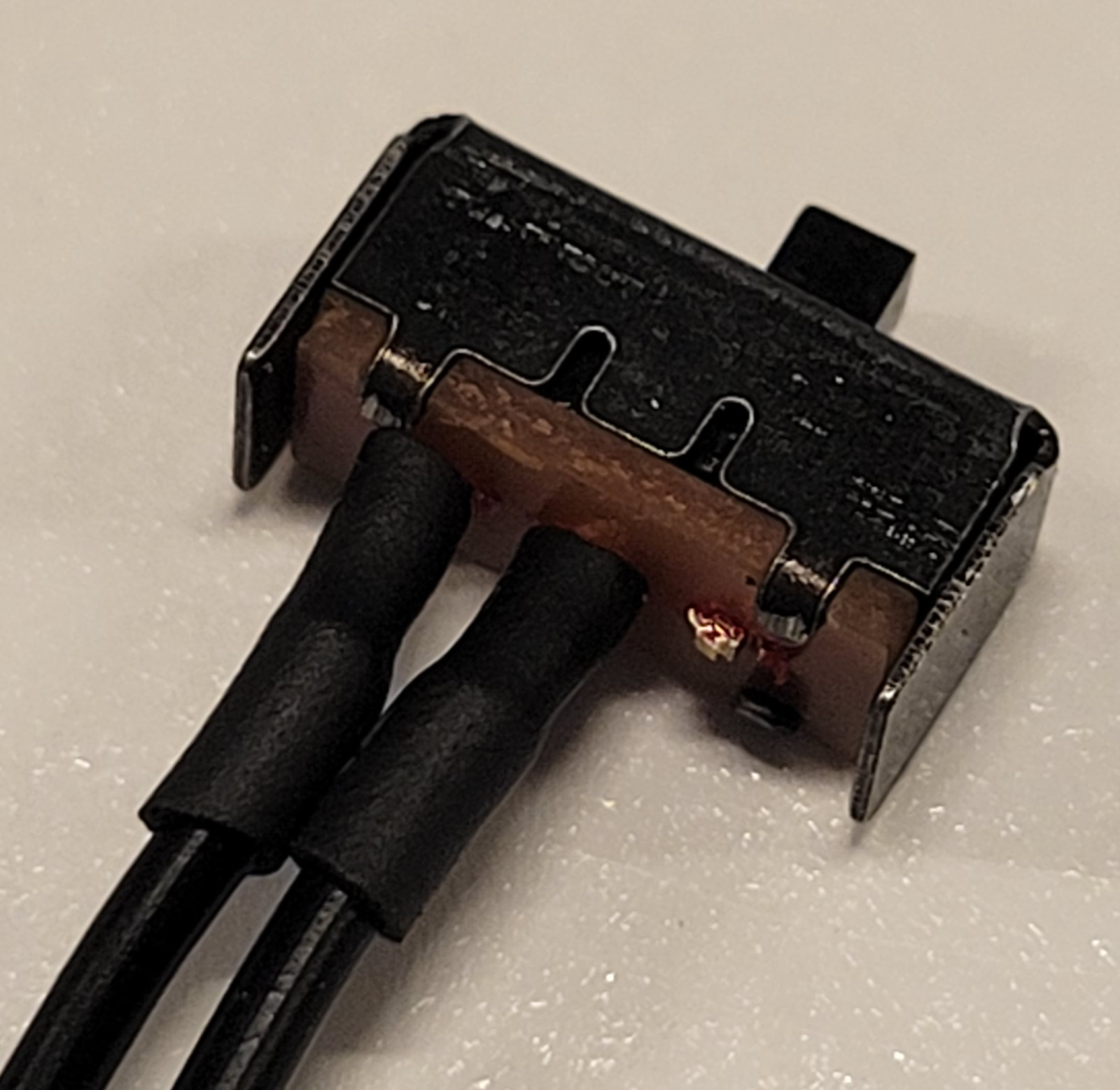
To save space inside the button, bend the button's metal connectors outwards. Be careful to only apply force to the metal connectors and not the inside of the button. Needle-nosed plyers come in handy.
We want to connect the Ground of the NeoPixel either of the button's metal connectors, and the continue a wire from there down to the ItsyBitsy. There are many ways to do this, but how I did it was to cut the ground wire running from the NeoPixel, strip it and run it through the little hole on the button's connector. Then I stripped another wire and ran that through the same hole, and soldered both wires to the metal connector.
We also need a wire from the other button connector down to the ItsyBitsy. Again, I stripped a wire, ran it through the hold and soldered it in place. These wires may get a fair bit of wear on them, so make sure the connections are well made. If I were going to do it again, I would have added Heat Shrink or some kind of glue to strengthen the connections.
Wiring up the circuit board
Check out this excellent guide on how solder wire to the pin holes. You'll be doing it quite a bit in this project.
The Power Switch
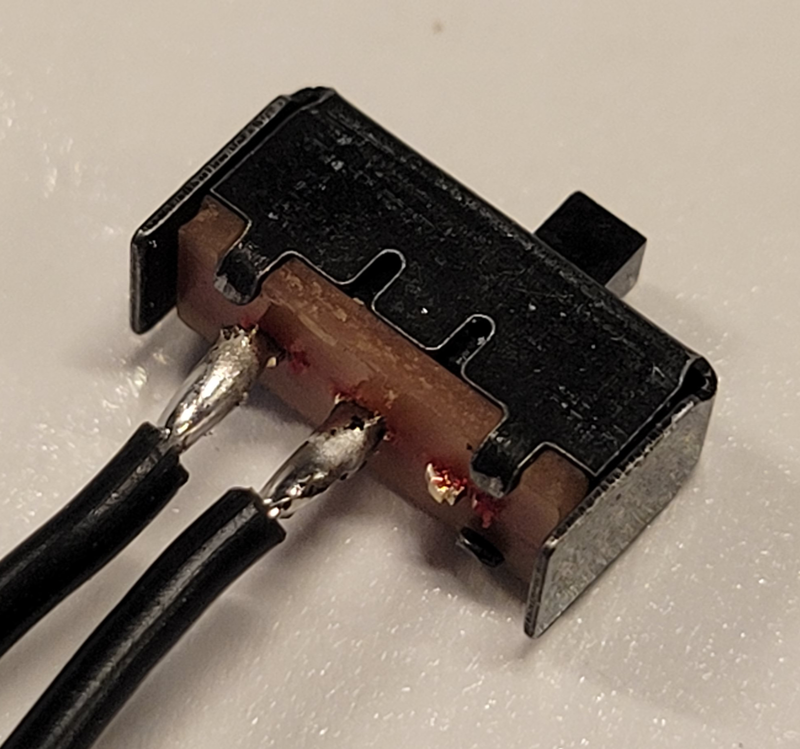
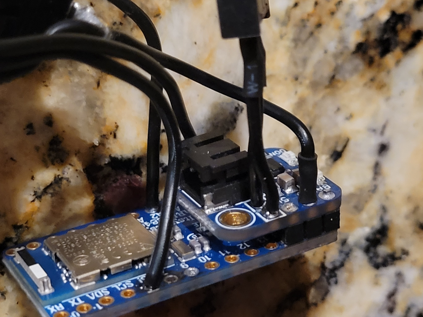
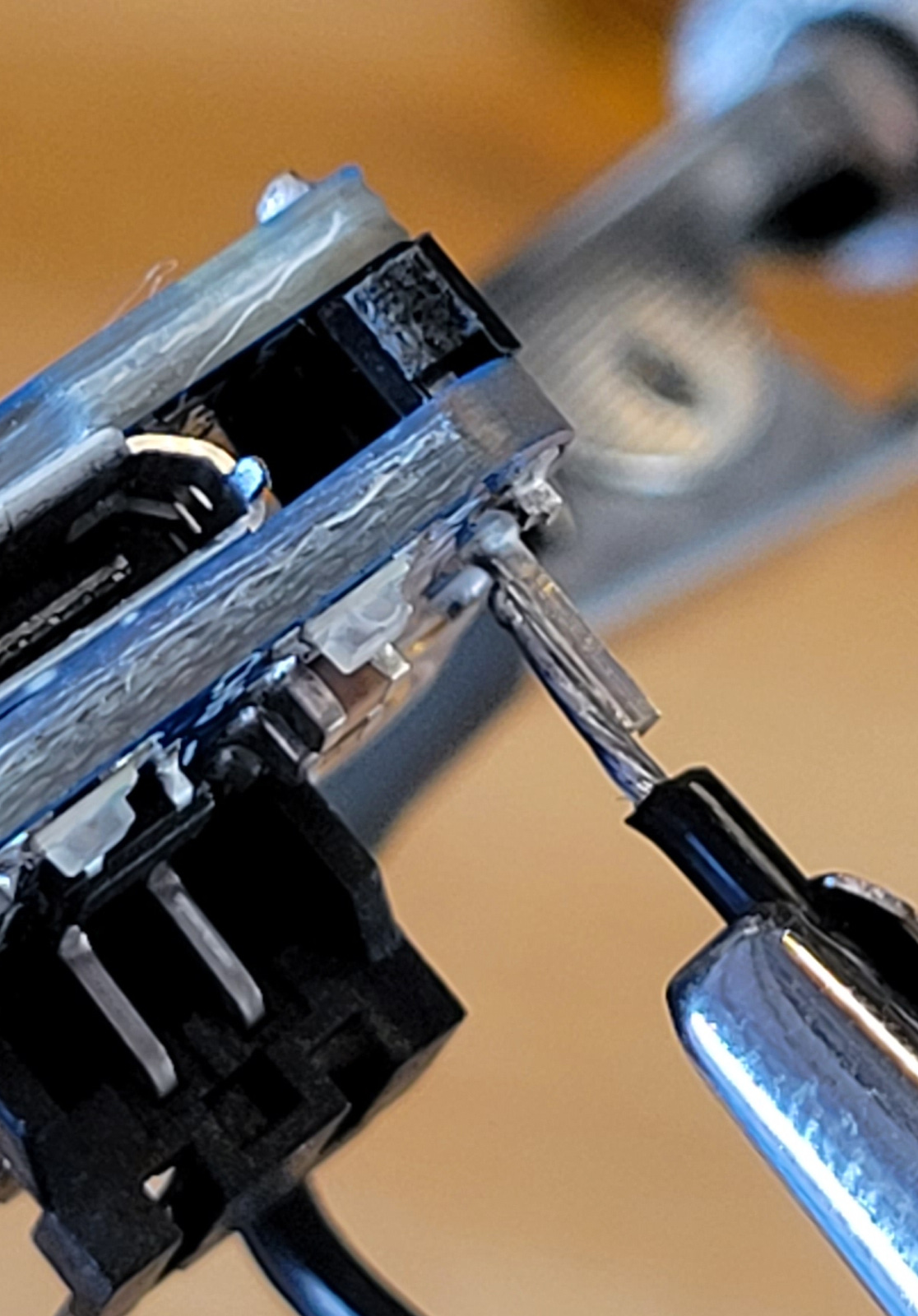
Shorten two of the legs on the power switch and solder wires to them, adding heat shrink afterwards. The third leg can be cut off entirely.
Next, cut the trace on the LiPo Backpack and then solder the power switch into the now separated pin holes.
The images show me doing this when I had already soldered the backpack to the ItsyBitsy, which made the soldering much harder! Do it the easy way and do this first before attaching it to the ItsyBitsy!
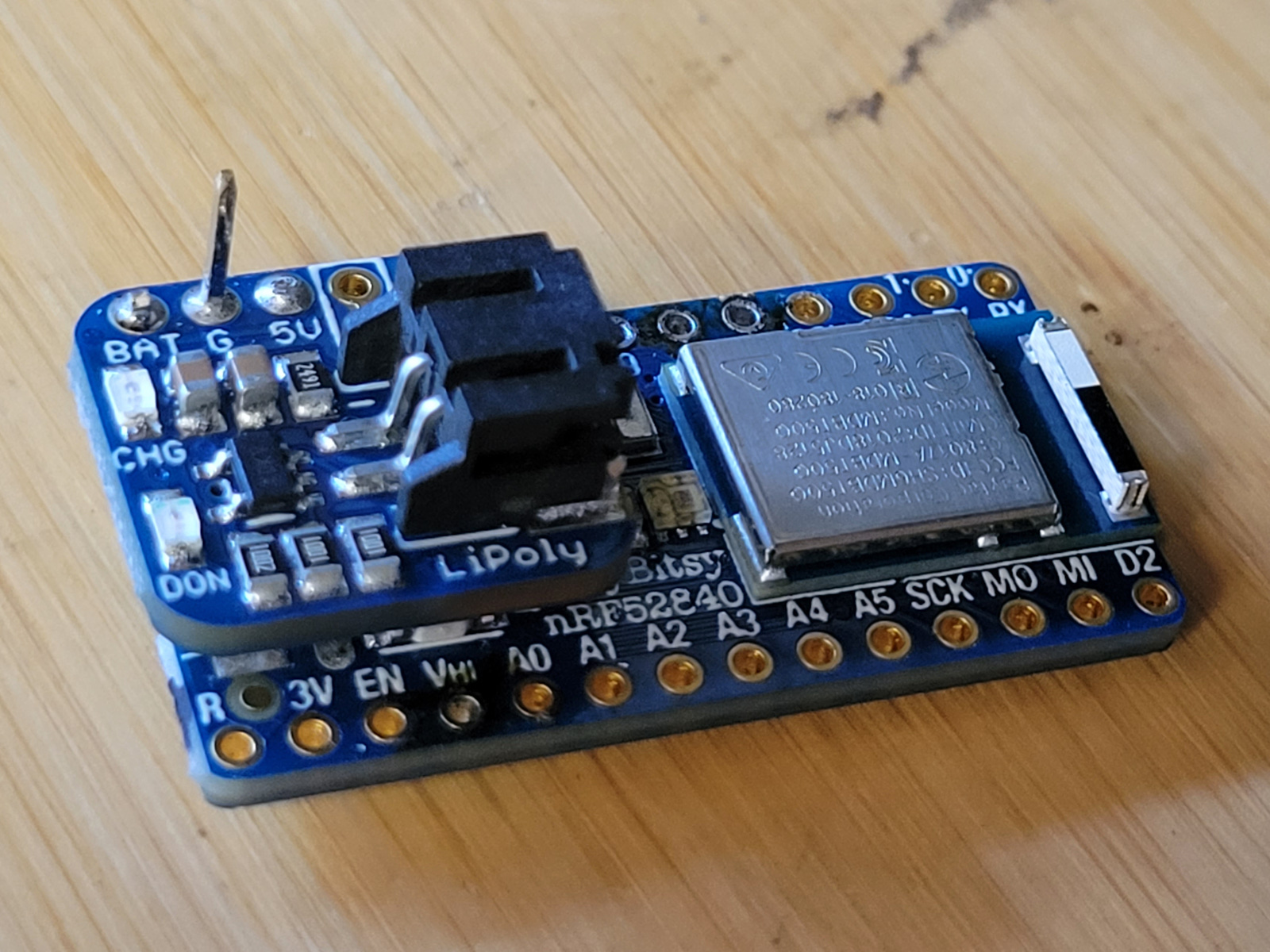
Connecting the Backpack to the ItsyBitsy
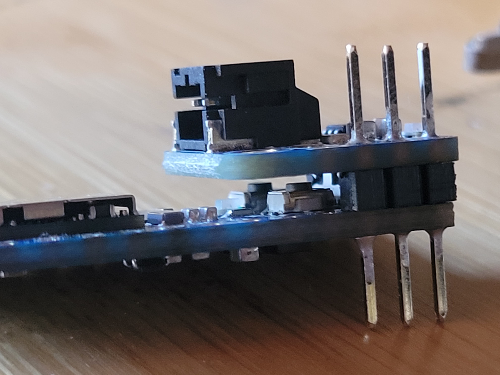
The backpack is made to sit on top of ItsyBitsy boards such that the header pins that come with it connects the two boards' power, ground and battery pins. Only, the Bluetooth ItsyBitsy has a couple of buttons that will get covered. Not a big deal since we only need to press the reset button once in order to load the CircuitPython boot loader. And, there is just enough clearance to still press the buttons if need be.
(in fact, skip ahead and load the CircuitPython boot loader before attaching the backpack.)
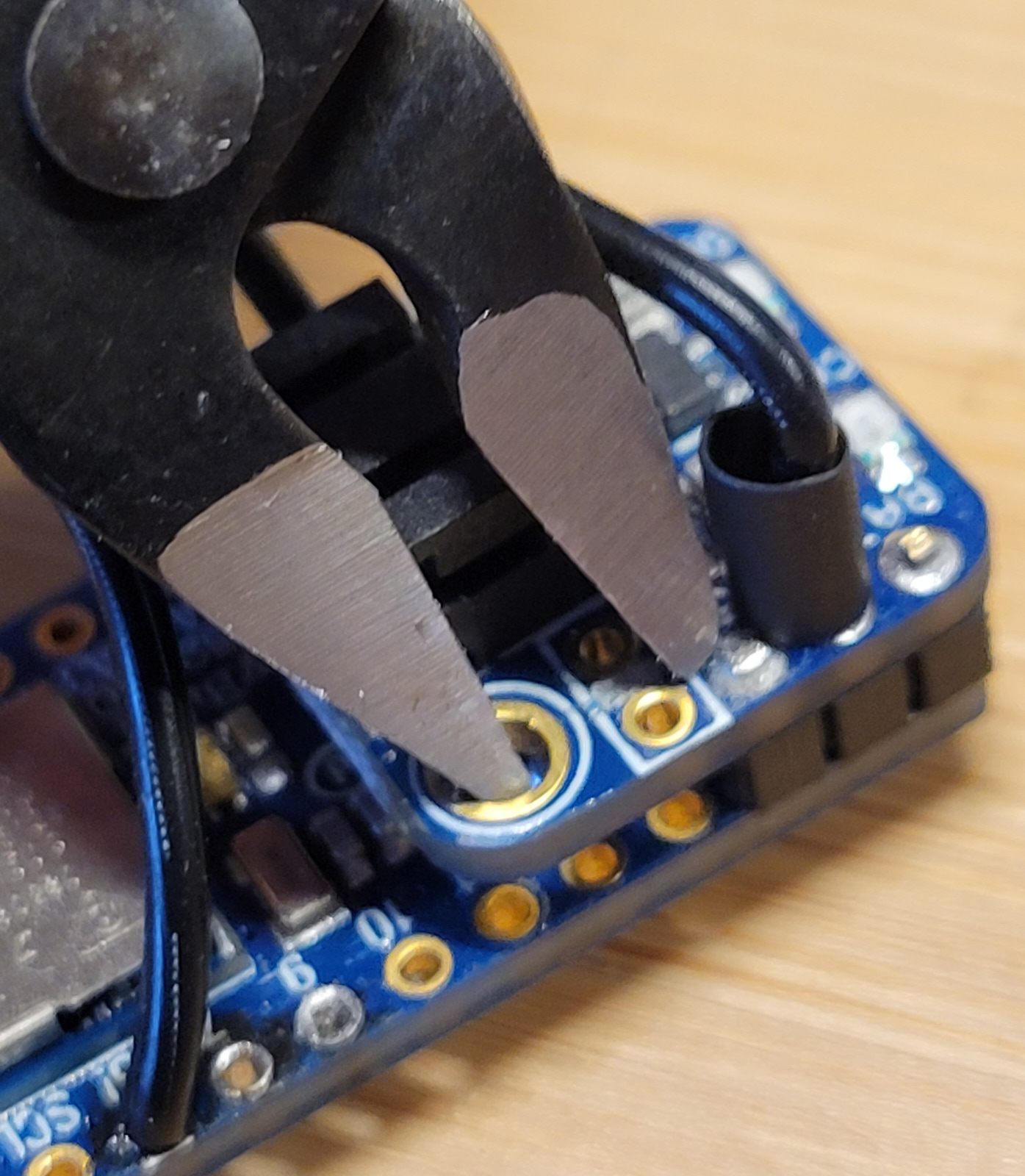
After we have soldered the two boards together, we use flush diagonal cutters to trim off the header pins but leave the Ground Pin uncut! This is the only ground we have on the ItsyBitsy, and we will need to run a wire from it to the button. In fact, you might as well solder that wire onto the pin right away, adding a heat shrink to it after you are done for stability.
Assembly without a lid
We have the button and the circuit board, both with loose wires hanging off them. It is now time to wire them together.
How long the wires should be is a matter of taste. Too long, and you start having crammed space inside the bottle. Too short and you might not have enough room to maneuver the board into the right place inside the bottle. I think I went a little short on my wires, but it works.
| ItsyBitsy | Button / NeoPixel | |
|---|---|---|
| G | Button & NeoPixel Ground | |
| Vhi | NeoPixel Power | |
| 5! | NeoPixel Signal In | |
| A? | Button 'Signal' |
You must wire the special signal pin 5! to the NeoPixel Signal In because it operates at the same voltage as the Vhi pin.
You can use any GPIO pin for the button switch. I picked A2 because it was in the middle of the ItsyBitsy, so no matter how I insert it into the bottle, the length of the wire will be OK.
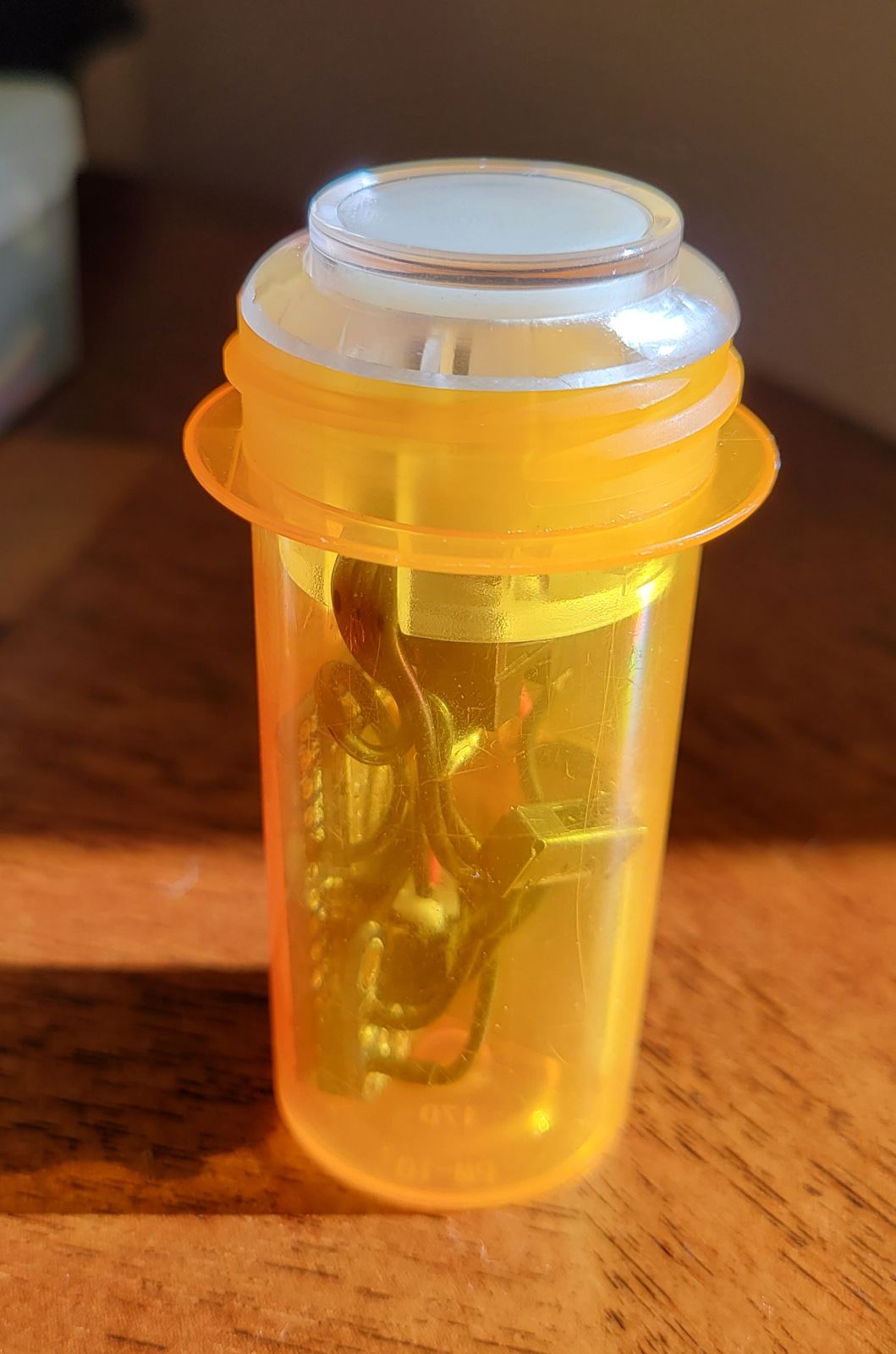
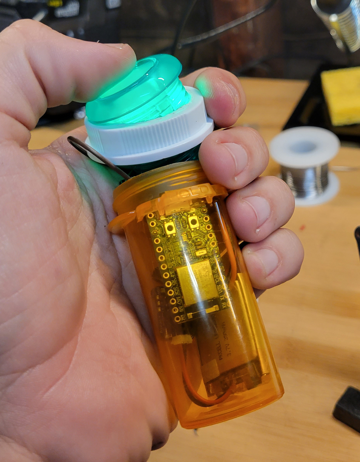
Once it is all wired up, simply insert it all into the bottle! It turned out that the size of the bottle I have was exactly right for the arcade button! Simply screw the button in like you would the lid. The plastic 'springs' on the side will hold on the to screw groves of the bottle. To open, simply screw it the other way. Magic!
Well, it was, until the plastic 'springs' one day snapped off. To fix it, or if your bottle doesn't fit as nicely, use the lid option below.
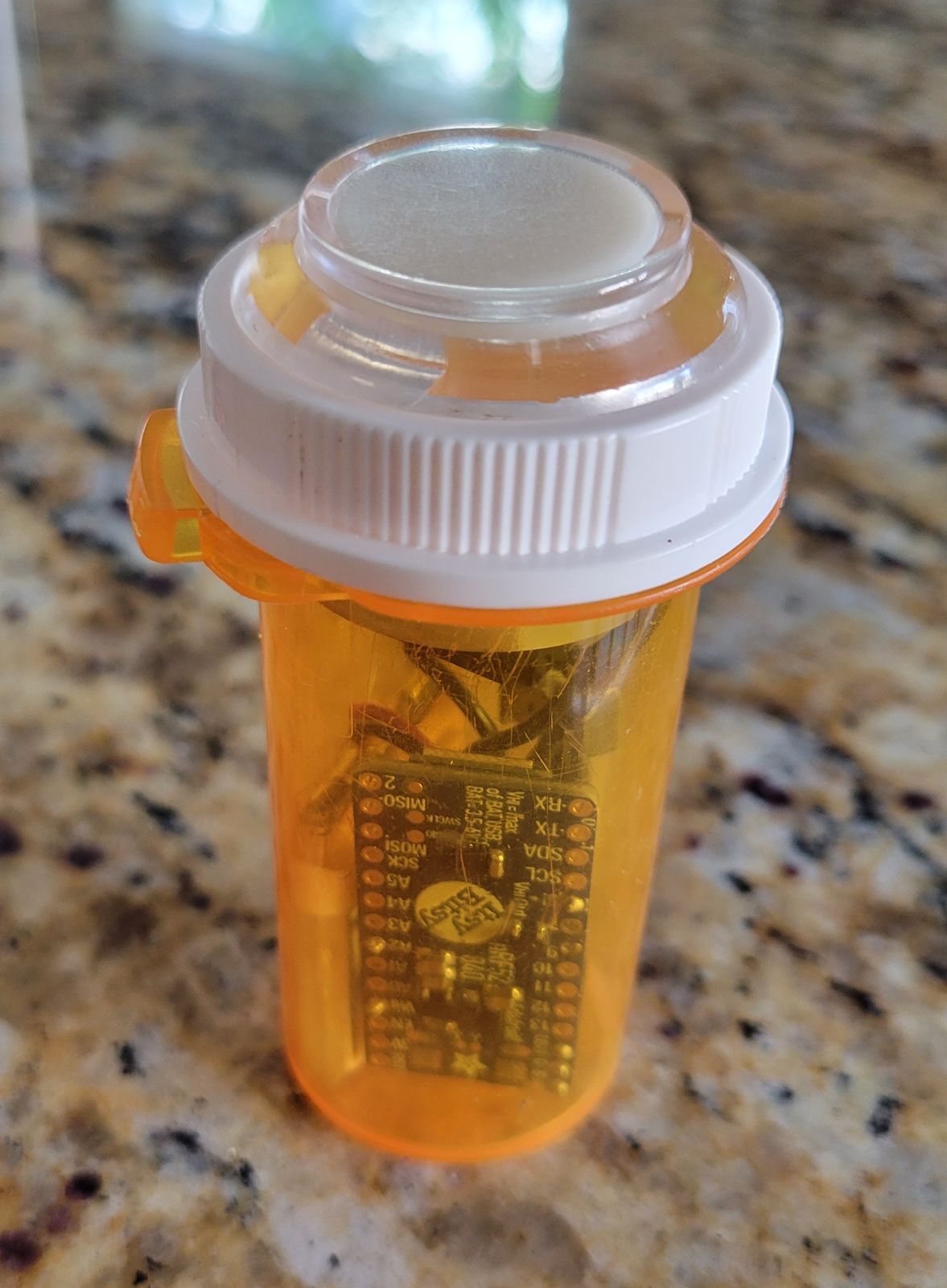
Assembly with a lid
If you have a bigger bottle, or the plastic springs break off, you can easily attach the arcade button to the lid of the pill bottle. You can then open and close the bottle simply by screwing and unscrewing the lid!
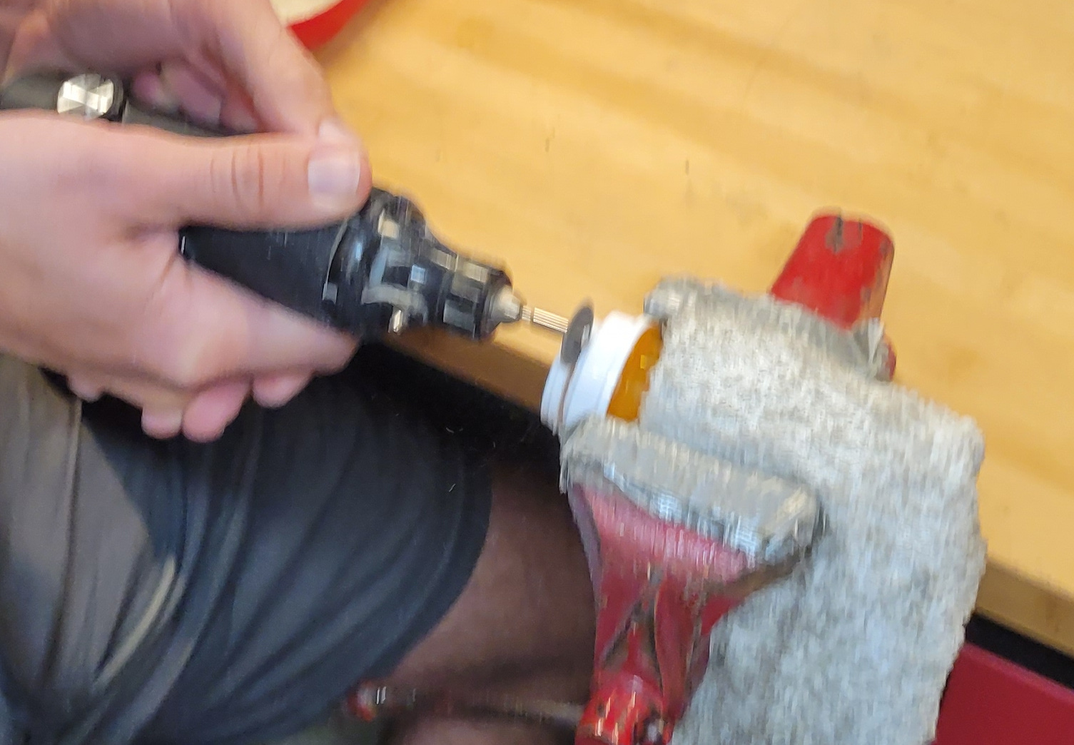
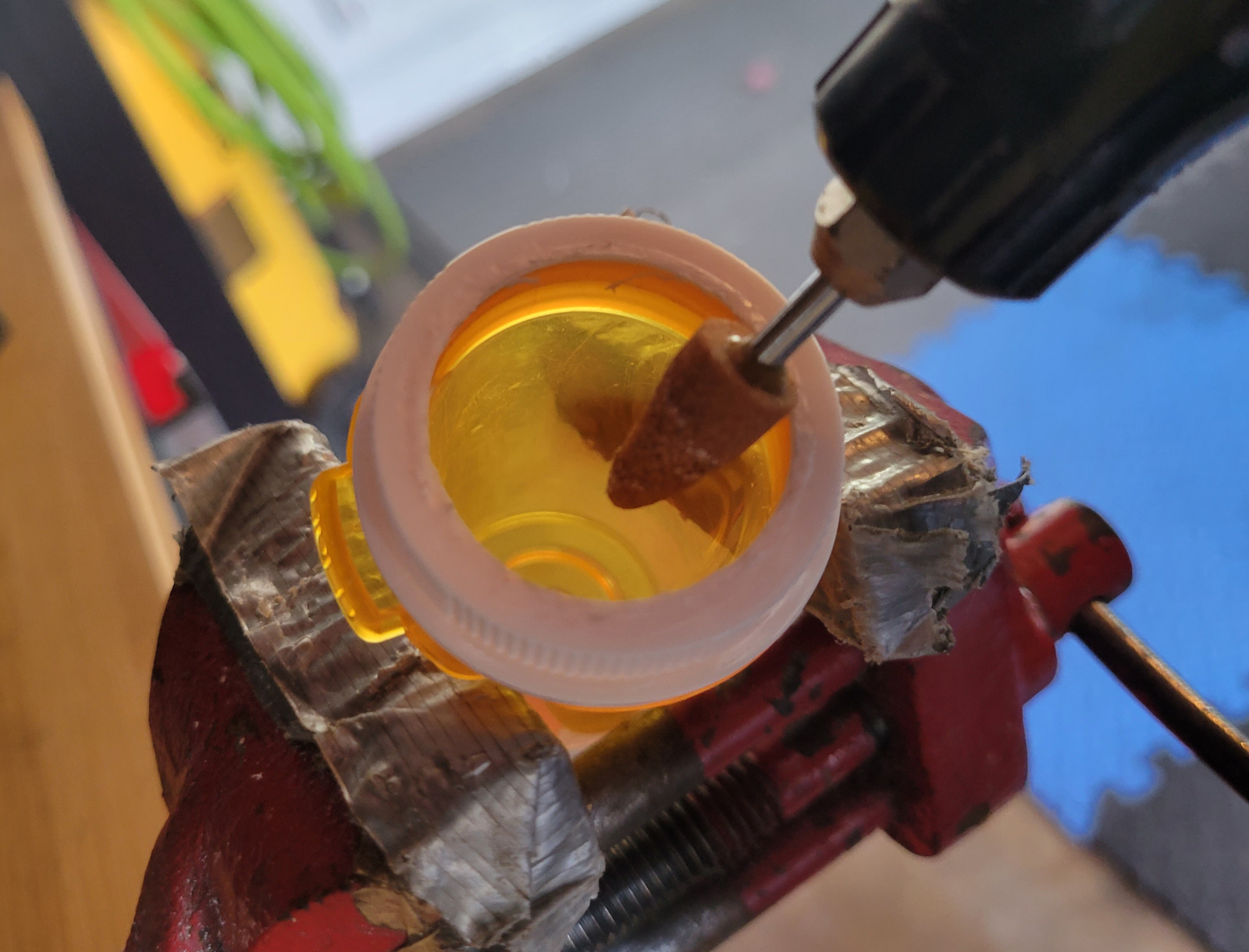
Somehow cut a hole in the lid. I used a dremel to first saw off the top part of the lid, then filed down the edges to make the hole just big enough for the button to slide in.
My hole was tight enough that the button stayed in place by friction alone, but a few drops of superglue under the lip of the button would have done the trick otherwise.
Programming the Pill Button
We will be programming the Pill Button using Circuit Python. There is a bit of setup to make this all work. I will assume that you know nothing about programming, and that your board is brand new.
- Install Circuit Python on your board by following this setup guide page. You should now have a disk drive called
CIRCUITPY. - Follow this guide to install some basic software libraries. You should have these installed under
/lib: adafruit_led_animation, adafruit_ble, adafruit_debouncer.mpy, neopixel.mpy. - Download the Pill Button's code.py file and copy it to the
CIRCUITPYdrive, overwriting the existing file. (safe-copy it if you like) - The top of the
code.pyfile has some variables that you can edit to customize how the remote works. You will find them between the comments saying '# Constants and Setup' and 'END OF THINGS YOU SHOULD MESS WITH'. Go ahead and play around with the variables. You can probably do this editing in any text editor, but I recommend you install the Mu Editor. See these pages for help on editing code: Installing the Mu Editor, Creating and Editing Code, Connecting to the Serial Console (if you want to see debug/error messages)
If you did all of the above, you should see the pill button blink blue, meaning it is ready to be connected to.
Connecting it to the Shared Game Timer
The Shared Game Timer Bluetooth connectivity is quite open-ended, able to connect to many different devices. This flexibility also means that the process of setting it up can be a bit confusing, but this step-by-step guide should hopefully help, and if you struggle, feel free to email me and I will be happy to assist.
Go to any Shared Game Timer game (feel free to create a toy one just to try it out), open the menu, open the Remote Control menu and click into the Bluetooth LE page.
Click the Device Configuration link.
If you have not yet added the Nordic UART service, click the 'Add Nordic UART' button.
You should now see the Service in the list of services. Click the button and you should be asked to connect to the Bluetooth device. Assuming the pill button is still blinking blue, you should see it available named something like 'Pill Button' or 'CIRCUITPY'. Click it and then Pair.
You should now see two sections, Write Script and Action Mapping. For more information about these sections, see the the Bluetooth Remote Control Overview page for more details.
The Shared Game Timer can ask the device for its preferred Write Script and Action Mapping by clicking the 'Request Setup Suggestion' button. This should populate the two sections. You should leave the Write Script as is, as sending the wrong commands will not work. The Actions Mapping, however, is only a suggestion, and you are free to edit it as you see fit. Remember to hit the 'Save' buttons on both sections.
The suggested 'Write Script' should be this:
0 sgtState;sgtColor;sgtTurnTime;sgtPlayerTime%0A
What it basically says is, "0 milliseconds after triggering, send the current game state, color and current turn time, followed by the new line character. For example, it might send pl;ff0033;150;300 . Give it a name and hit Save.
Now look at the Action Mapping section. In the 'Log' you will see all the events sent from the Clue to the Shared Game Timer. Try pressing the button. You should see 'Short Press 1'. Press it twice quickly. You should see 'Short Press 2'. Try long-pressing the button. You should see 'Long Press 0'. Why zero? Because the number is always the number of short-presses made. Try pressing once and then long press. You'll get 'Long Press 1'. So the number comes from the number of short-presses made, and you'll either get 'Long' or 'Short' Press depending on if the last press was long or short.
There is one more keyword. 'Connected' is sent as soon as the Pill Button connects to the Shared Game Timer. You should always map this keyword to the action 'Poll' so the Pill Button can ask for the Shared Game Timer state as soon as it connects.
When defining keywords for your action map, remember that the Shared Game Timer will evaluate each of the action mappings in order and trigger the first one that contains the keyword.
So if you add a keyword of 'Short Press', it will match any number of short presses ('Short Press 1, 'Short Press 2 etc) Therefore it must go after for example 'Short Press 1'.
We are now all done to use the button! Go back to the Bluetooth Remote page, and you should see the Write Script and Activation Map we just created. Activate both. For the Write Script, click the 'Tick all checkboxes' button, and also tick the 'Whenever target state becomes active' as well as 'When Polled'. Finally, click Connect and you are now DONE! 🥳
Possible Improvements
To turn the button on or off, or to program it, you must open the lid and pull out the insides. It would be nice to make a small hole in the bottom of the bottle and set the power switch there, or possible a small hole for the USB connection.
Also, I tried to fit a vibrating motor disk or a small speaker into it to provide some feedback other than light, but there wasn't enough space. A larger bottle might accommodate this however.